
Videos
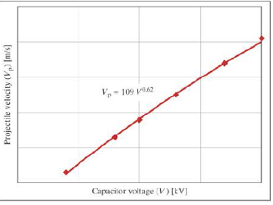
- 14. The data shown in the following graph was collected during testing of an electromagnetic mass driver. The energy to energize the electromagnets was obtained from a bank of capacitors. The capacitor bank was charged to various voltages, and for each voltage, the exit velocity of the projectile was measured when the mass driver was activated.
-
Note
Due to several complicated nonlinear losses in the system that are far beyond the
scope of this course, this is a case of a power model in which the exponent does not come out to be an integer or simple fraction, so rounding to two significant figures is appropriate. In fact, this model is only a first approximation-a really accurate model would be considerably more complicated.
-
- a. What would the velocity be if the capacitors were charged to 100,000 volts?
- b. What voltage would be necessary to accelerate the projectile to 1000 meters per second?
- c. Assume that the total capacitance is 5 farads. If the capacitors are initially charged to 10,000 volts and are discharged to 2000 volts during the launch of a projectile, what is the mass of the projectile if the overall conversion of energy stored in the capacitors to kinetic energy in the projectile has an efficiency of 20%? Recall that the energy stored in a capacitor is given by E = 0.5 CV2, where C is capacitance in farads and V is voltage in volts.

Trending nowThis is a popular solution!

Learn your wayIncludes step-by-step video

Chapter 12 Solutions
THINKING LIKE AN ENGINEER W/ACCESS
Additional Engineering Textbook Solutions
Starting Out With Visual Basic (8th Edition)
Java How to Program, Early Objects (11th Edition) (Deitel: How to Program)
Electric Circuits. (11th Edition)
Degarmo's Materials And Processes In Manufacturing
Fluid Mechanics: Fundamentals and Applications
Mechanics of Materials (10th Edition)


- 2. Solve the following linear time invariant differential equations using Laplace transforms subject to different initial conditions (a) y-y=t for y(0) = 1 and y(0) = 1 (b) ÿ+4y+ 4y = u(t) for y(0) = 0 and y(0) = 1 (c) y-y-2y=0 for y(0) = 1 and y(0) = 0arrow_forward3. For the mechanical systems shown below, the springs are undeflected when x₁ = x2 = x3 = 0 and the input is given as fa(t). Draw the free-body diagrams and write the modeling equations governing each of the systems. K₁ 000 K₂ 000 M₁ M2 -fa(t) B₂ B₁ (a) fa(t) M2 K₂ 000 B K₁ x1 000 M₁ (b)arrow_forwardThis question i m uploading second time . before you provide me incorrect answer. read the question carefully and solve accordily.arrow_forward
- 1. Create a table comparing five different analogous variables for translational, rotational, electrical and fluid systems. Include the standard symbols for each variable in their respective systems.arrow_forward2) Suppose that two unequal masses m₁ and m₂ are moving with initial velocities v₁ and v₂, respectively. The masses hit each other and have a coefficient of restitution e. After the impact, mass 1 and 2 head to their respective gaps at angles a and ẞ, respectively. Derive expressions for each of the angles in terms of the initial velocities and the coefficient of restitution. m1 m2 8 m1 m2 βarrow_forward4. Find the equivalent spring constant and equivalent viscous-friction coefficient for the systems shown below. @ B₁ B₂ H B3 (b)arrow_forward
- 5. The cart shown below is inclined 30 degrees with respect to the horizontal. At t=0s, the cart is released from rest (i.e. with no initial velocity). If the air resistance is proportional to the velocity squared. Analytically determine the initial acceleration and final or steady-state velocity of the cart. Take M= 900 kg and b 44.145 Ns²/m². Mg -bx 2 отarrow_forward9₁ A Insulated boundary Insulated boundary dx Let's begin with the strong form for a steady-state one-dimensional heat conduction problem, without convection. d dT + Q = dx dx According to Fourier's law of heat conduction, the heat flux q(x), is dT q(x)=-k dx. x Q is the internal heat source, which heat is generated per unit time per unit volume. q(x) and q(x + dx) are the heat flux conducted into the control volume at x and x + dx, respectively. k is thermal conductivity along the x direction, A is the cross-section area perpendicular to heat flux q(x). T is the temperature, and is the temperature gradient. dT dx 1. Derive the weak form using w(x) as the weight function. 2. Consider the following scenario: a 1D block is 3 m long (L = 3 m), with constant cross-section area A = 1 m². The left free surface of the block (x = 0) is maintained at a constant temperature of 200 °C, and the right surface (x = L = 3m) is insulated. Recall that Neumann boundary conditions are naturally satisfied…arrow_forward1 - Clearly identify the system and its mass and energy exchanges between each system and its surroundings by drawing a box to represent the system boundary, and showing the exchanges by input and output arrows. You may want to search and check the systems on the Internet in case you are not familiar with their operations. A pot with boiling water on a gas stove A domestic electric water heater A motor cycle driven on the roadfrom thermodynamics You just need to draw and put arrows on the first part a b and carrow_forward
- 7. A distributed load w(x) = 4x1/3 acts on the beam AB shown in Figure 7, where x is measured in meters and w is in kN/m. The length of the beam is L = 4 m. Find the moment of the resultant force about the point B. w(x) per unit length L Figure 7 Barrow_forward4. The press in Figure 4 is used to crush a small rock at E. The press comprises three links ABC, CDE and BG, pinned to each other at B and C, and to the ground at D and G. Sketch free-body diagrams of each component and hence determine the force exerted on the rock when a vertical force F = 400 N is applied at A. 210 80 80 C F 200 B 80 E 60% -O-D G All dimensions in mm. Figure 4arrow_forward2. Figure 2 shows a device for lifting bricks and concrete blocks. It comprises two compo- nents ABC and BD, with a frictionless pin at B. Determine the minimum coefficient of friction required at A and D if the device is to work satisfactorily. W all dimensions in inches Figure 2 Darrow_forward
 Automotive Technology: A Systems Approach (MindTa...Mechanical EngineeringISBN:9781133612315Author:Jack Erjavec, Rob ThompsonPublisher:Cengage Learning
 Refrigeration and Air Conditioning Technology (Mi...Mechanical EngineeringISBN:9781305578296Author:John Tomczyk, Eugene Silberstein, Bill Whitman, Bill JohnsonPublisher:Cengage Learning