Mechanics of Materials, Student Value Edition Plus Mastering Engineering with Pearson eText -- Access Card Package (10th Edition)
10th Edition
ISBN: 9780134326054
Author: Russell C. Hibbeler
Publisher: PEARSON
expand_more
expand_more
format_list_bulleted
Concept explainers
Videos
Textbook Question
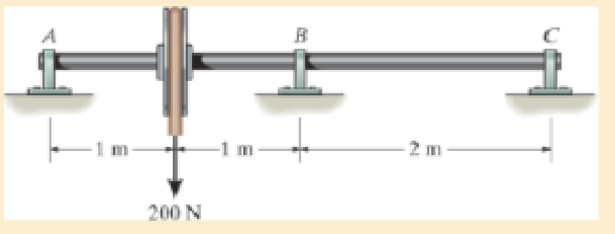
Chapter 12, Problem 12.7RP
Determine the reactions, then draw the shear and moment diagrams. Use the moment-area theorems. El is constant.
Expert Solution & Answer
Want to see the full answer?
Check out a sample textbook solution
Students have asked these similar questions
An unpressurized cylindrical tank with a 100-foot diameter holds a 40-foot column of water. What is total force acting against the bottom of the tank?
7. In the following problems check to see if the set S is a vector subspace of the corresponding
R. If it is not, explain why not. If it is, then find a basis and the dimension.
(a) S
=
(b) S =
{[],+,"}
X1
x12x2 = x3
CR³
{[1], 4+4 = 1} CR³
X2
AAA
Show laplace transform on 1; (+) to L (y(+)) : SY(s) = x (0)
Y(s) = £ [lx (+)] = 5 x(+) · est de
2
-St
L [ y (^) ] = So KG) et de
D
2
D
D
AA
Y(A) → Y(s)
Ŷ (+) → s Y(s)
-y
Chapter 12 Solutions
Mechanics of Materials, Student Value Edition Plus Mastering Engineering with Pearson eText -- Access Card Package (10th Edition)
Ch. 12.2 - In each case, determine the internal bending...Ch. 12.2 - Determine the slope and deflection of end A of the...Ch. 12.2 - Determine the slope and deflection of end A of the...Ch. 12.2 - Determine the slope of end A of the cantilevered...Ch. 12.2 - Determine the maximum deflection of the simply...Ch. 12.2 - Determine the maximum deflection of the simply...Ch. 12.2 - Determine the slope of the simply supported beam...Ch. 12.2 - An L2 steel strap having a thickness of 0.125 in....Ch. 12.2 - The L2 steel blade of the band saw wraps around...Ch. 12.2 - A picture is taken of a man performing a pole...
Ch. 12.2 - El is constant. Prob. 124Ch. 12.2 - Determine the deflection of end C of the...Ch. 12.2 - Determine the elastic curve for the cantilevered...Ch. 12.2 - The A-36 steel beam has a depth of 10 in. and is...Ch. 12.2 - Determine the equations of the elastic curve using...Ch. 12.2 - Determine the equations of the elastic curve for...Ch. 12.2 - Determine the equations of the elastic curve using...Ch. 12.2 - Determine the equations of the elastic curve using...Ch. 12.2 - Draw the bending-moment diagram for the shaft and...Ch. 12.2 - Determine the maximum deflection of the beam and...Ch. 12.2 - The simply supported shaft has a moment of inertia...Ch. 12.2 - A torque wrench is used to tighten the nut on a...Ch. 12.2 - The pipe can be assumed roller supported at its...Ch. 12.2 - Determine the equations of the elastic curve for...Ch. 12.2 - The bar is supported by a roller constraint at B,...Ch. 12.2 - Determine the deflection at B of the bar in Prob....Ch. 12.2 - Determine the equations of the elastic curve using...Ch. 12.2 - Determine the maximum deflection of the solid...Ch. 12.2 - Determine the elastic curve for the cantilevered...Ch. 12.2 - Determine the equations of the elastic curve using...Ch. 12.2 - Determine the equations of the elastic curve using...Ch. 12.2 - The floor beam of the airplane is subjected to the...Ch. 12.2 - Determine the maximum deflection of the simply...Ch. 12.2 - The beam is made of a material having a specific...Ch. 12.2 - Determine the slope at end B and the maximum...Ch. 12.2 - Determine the equation of the elastic curve using...Ch. 12.2 - Determine the equations of the elastic curve using...Ch. 12.3 - The shaft is supported at A by a journal bearing...Ch. 12.3 - The shaft supports the two pulley loads shown....Ch. 12.3 - The beam is made of a ceramic material. If it is...Ch. 12.3 - Determine the equation of the elastic curve, the...Ch. 12.3 - The beam is subjected to the load shown. Determine...Ch. 12.3 - Determine the equation of the elastic curve, the...Ch. 12.3 - Determine the equation of the elastic curve and...Ch. 12.3 - The shaft supports the two pulley loads. Determine...Ch. 12.3 - Determine the maximum deflection of the...Ch. 12.3 - Determine the slope at A and the deflection of end...Ch. 12.3 - Determine the maximum deflection in region AB of...Ch. 12.3 - Prob. 12.42PCh. 12.3 - Prob. 12.43PCh. 12.3 - Prob. 12.44PCh. 12.3 - Prob. 12.45PCh. 12.3 - Prob. 12.46PCh. 12.3 - Prob. 12.47PCh. 12.3 - Determine the value of a so that the displacement...Ch. 12.3 - Determine the displacement at C and the slope at...Ch. 12.3 - Determine the equations of the slope and elastic...Ch. 12.4 - Determine the slope and deflection of end A of the...Ch. 12.4 - Determine the slope and deflection of end A of the...Ch. 12.4 - Determine the slope and deflection of end A of the...Ch. 12.4 - Determine the slope and deflection at A of the...Ch. 12.4 - Prob. 12.11FPCh. 12.4 - Determine the maximum deflection of the simply...Ch. 12.4 - Determine the slope and deflection at C. El is...Ch. 12.4 - Determine the slope and deflection at C. El is...Ch. 12.4 - Determine the deflection of end B of the...Ch. 12.4 - Prob. 12.54PCh. 12.4 - The composite simply supported steel shaft is...Ch. 12.4 - Prob. 12.56PCh. 12.4 - Prob. 12.57PCh. 12.4 - Determine the deflection at C and the slope of the...Ch. 12.4 - Determine the maximum deflection of the...Ch. 12.4 - Prob. 12.60PCh. 12.4 - Determine the position a of the roller support B...Ch. 12.4 - Prob. 12.62PCh. 12.4 - Determine the slope and the deflection of end B of...Ch. 12.4 - The two A-36 steel bars have a thickness of 1 in....Ch. 12.4 - Determine the slope at A and the displacement at...Ch. 12.4 - Determine the deflection at C and the slopes at...Ch. 12.4 - Determine the maximum deflection within region AB....Ch. 12.4 - Determine the slope at A and the maximum...Ch. 12.4 - Determine the slope at C and the deflection at B....Ch. 12.4 - Determine the slope at A and the maximum...Ch. 12.4 - Determine the displacement of the 20-mm-diameter...Ch. 12.4 - The two force components act on the tire of the...Ch. 12.4 - Prob. 12.73PCh. 12.4 - The rod is constructed from two shafts for which...Ch. 12.4 - Prob. 12.75PCh. 12.4 - Determine the slope at point A and the maximum...Ch. 12.4 - Determine the position a of roller support B in...Ch. 12.4 - Determine the slope at B and deflection at C. El...Ch. 12.4 - Prob. 12.79PCh. 12.4 - Prob. 12.80PCh. 12.4 - Prob. 12.81PCh. 12.4 - Determine the maximum deflection of the beam. El...Ch. 12.5 - The W10 15 cantilevered beam is made of A-36...Ch. 12.5 - The W10 15 cantilevered beam is made of A-36...Ch. 12.5 - The W14 43 simply supported beam is made of A992...Ch. 12.5 - The W14 43 simply supported beam is made of A992...Ch. 12.5 - The W14 43 simply supported beam is made of A-36...Ch. 12.5 - The W14 43 simply supported beam is made of A-36...Ch. 12.5 - The W8 48 cantilevered beam is made of A-36 steel...Ch. 12.5 - The beam supports the loading shown. Code...Ch. 12.5 - The W24 104 A-36 steel beam is used to support...Ch. 12.5 - The W8 48 cantilevered beam is made of A-36 steel...Ch. 12.5 - The rod is pinned at its end A and attached to a...Ch. 12.5 - Prob. 12.94PCh. 12.5 - The pipe assembly consists of three equal-sized...Ch. 12.5 - The assembly consists of a cantilevered beam CS...Ch. 12.5 - Determine the smallest force F required to attract...Ch. 12.5 - Prob. 12.98PCh. 12.7 - Determine the reactions at the supports A and B,...Ch. 12.7 - Determine the reactions at the supports, then draw...Ch. 12.7 - Determine the reactions at the supports A, B, and...Ch. 12.7 - Determine the reactions at the supports A and B,...Ch. 12.7 - Determine the reactions at the supports A and B,...Ch. 12.7 - Determine the moment reactions at the supports A...Ch. 12.7 - Determine the reactions at the supports A and B,...Ch. 12.7 - Determine the reactions at the support A and B. EI...Ch. 12.7 - Determine the reactions at roller support A and...Ch. 12.7 - Determine the moment reactions at the supports A...Ch. 12.7 - The beam has a constant E1I1 and is supported by...Ch. 12.7 - The beam is supported by a pin at A, a roller at...Ch. 12.8 - Determine the moment reactions at the supports A...Ch. 12.8 - Determine the reaction at the supports, then draw...Ch. 12.8 - Determine the vertical reaction at the journal...Ch. 12.8 - Determine the reactions at the supports A and B,...Ch. 12.8 - Determine the reactions at the supports. EI is...Ch. 12.8 - Determine the vertical reaction at the journal...Ch. 12.9 - Determine the reactions at the fixed support A and...Ch. 12.9 - Determine the reactions at the fixed support A and...Ch. 12.9 - Determine the reactions at the fixed support A and...Ch. 12.9 - Determine the reaction at the roller B. EI is...Ch. 12.9 - Determine the reaction at the roller B. EI is...Ch. 12.9 - Determine the reaction at the roller support B if...Ch. 12.9 - Determine the reactions at the journal bearing...Ch. 12.9 - Determine the reactions at the supports, then draw...Ch. 12.9 - Determine the reactions at the supports, then draw...Ch. 12.9 - Determine the reactions at the supports A and B....Ch. 12.9 - The beam is used to support the 20-kip load....Ch. 12.9 - Determine the reactions at the supports A and B....Ch. 12.9 - Determine the reactions at the supports A and B....Ch. 12.9 - Before the uniform distributed load is applied to...Ch. 12.9 - The fixed supported beam AB is strengthened using...Ch. 12.9 - The beam has a constant E1I1, and is supported by...Ch. 12.9 - The beam is supported by the bolted supports at...Ch. 12.9 - Each of the two members is made from 6061-T6...Ch. 12.9 - The beam is made from a soft linear elastic...Ch. 12.9 - The beam AB has a moment of inertia I = 475 in4...Ch. 12.9 - The rim on the flywheel has a thickness t, width...Ch. 12.9 - Determine the moment developed in each corner....Ch. 12 - Determine the equation of the elastic curve. Use...Ch. 12 - Draw the bending-moment diagram for the shaft and...Ch. 12 - Determine the moment reactions at the supports A...Ch. 12 - Specify the slope at A and the maximum deflection....Ch. 12 - Determine the maximum deflection between the...Ch. 12 - Determine the slope at B and the deflection at C....Ch. 12 - Determine the reactions, then draw the shear and...Ch. 12 - El is constant.Ch. 12 - Using the method of superposition, determine the...
Additional Engineering Textbook Solutions
Find more solutions based on key concepts
In Exercises 1 through 22, determine the output displayed in the text box or list box by the lines of code.
Introduction To Programming Using Visual Basic (11th Edition)
Convert each of the following binary representations to its equivalent base ten form: a. 101010 b. 100001 c. 10...
Computer Science: An Overview (13th Edition) (What's New in Computer Science)
Computers process data under the control of sets of instructions called
Java How to Program, Early Objects (11th Edition) (Deitel: How to Program)
Comprehension Check 7-14
The power absorbed by a resistor can be given by P = I2R, where P is power in units of...
Thinking Like an Engineer: An Active Learning Approach (4th Edition)
Write a summary list of the problem-solving steps identified in the chapter, using your own words.
BASIC BIOMECHANICS
Why is the study of database technology important?
Database Concepts (8th Edition)
Knowledge Booster


Learn more about
Need a deep-dive on the concept behind this application? Look no further. Learn more about this topic, mechanical-engineering and related others by exploring similar questions and additional content below.Similar questions
- 1) In each of the following scenarios, based on the plane of impact (shown with an (n, t)) and the motion of mass 1, draw the direction of motion of mass 2 after the impact. Note that in all scenarios, mass 2 is initially at rest. What can you say about the nature of the motion of mass 2 regardless of the scenario? m1 15 <+ m2 2) y "L χ m1 m2 m1 בז m2 Farrow_forward8. In the following check to see if the set S is a vector subspace of the corresponding Rn. If it is not, explain why not. If it is, then find a basis and the dimension. X1 (a) S = X2 {[2], n ≤ n } c X1 X2 CR² X1 (b) S X2 = X3 X4 x1 + x2 x3 = 0arrow_forward2) Suppose that two unequal masses m₁ and m₂ are moving with initial velocities V₁ and V₂, respectively. The masses hit each other and have a coefficient of restitution e. After the impact, mass 1 and 2 head to their respective gaps at angles a and ẞ, respectively. Derive expressions for each of the angles in terms of the initial velocities and the coefficient of restitution. m1 m2 8 m1 ↑ บา m2 ñ Вarrow_forward
- The fallowing question is from a reeds book on applied heat i am studying. Although the answer is provided, im struggling to understand the whole answer and the formulas and the steps theyre using. Also where some ov the values such as Hg and Hf come from in part i for example. Please explain step per step in detail thanks In an NH, refrigerator, the ammonia leaves the evaporatorand enters the cornpressor as dry saturated vapour at 2.68 bar,it leaves the compressor and enters the condenser at 8.57 bar with50" of superheat. it is condensed at constant pressure and leavesthe condenser as saturated liquid. If the rate of flow of the refrigerantthrough the circuit is 0.45 kglmin calculate (i) the compressorpower, (ii) the heat rejected to the condenser cooling water in kJ/s,an (iii) the refrigerating effect in kJ/s. From tables page 12, NH,:2.68 bar, hg= 1430.58.57 bar, hf = 275.1 h supht 50" = 1597.2Mass flow of refrigerant--- - - 0.0075 kgls 60Enthalpy gain per kg of refrigerant in…arrow_forwardstate the formulas for calculating work done by gasarrow_forwardExercises Find the solution of the following Differential Equations 1) y" + y = 3x² 3) "+2y+3y=27x 5) y"+y=6sin(x) 7) y"+4y+4y = 18 cosh(x) 9) (4)-5y"+4y = 10 cos(x) 11) y"+y=x²+x 13) y"-2y+y=e* 15) y+2y"-y'-2y=1-4x³ 2) y"+2y' + y = x² 4) "+y=-30 sin(4x) 6) y"+4y+3y=sin(x)+2 cos(x) 8) y"-2y+2y= 2e* cos(x) 10) y+y-2y=3e* 12) y"-y=e* 14) y"+y+y=x+4x³ +12x² 16) y"-2y+2y=2e* cos(x)arrow_forward
- The state of stress at a point is σ = -4.00 kpsi, σy = 16.00 kpsi, σ = -14.00 kpsi, Try = 11.00 kpsi, Tyz = 8.000 kpsi, and T = -14.00 kpsi. Determine the principal stresses. The principal normal stress σ₁ is determined to be [ The principal normal stress σ2 is determined to be [ The principal normal stress σ3 is determined to be kpsi. kpsi. The principal shear stress 71/2 is determined to be [ The principal shear stress 7½ is determined to be [ The principal shear stress T₁/, is determined to be [ kpsi. kpsi. kpsi. kpsi.arrow_forwardRepeat Problem 28, except using a shaft that is rotatingand transmitting a torque of 150 N * m from the left bearing to the middle of the shaft. Also, there is a profile keyseat at the middle under the load. (I want to understand this problem)arrow_forwardProb 2. The material distorts into the dashed position shown. Determine the average normal strains &x, Ey and the shear strain Yxy at A, and the average normal strain along line BE. 50 mm B 200 mm 15 mm 30 mm D ΕΙ 50 mm x A 150 mm Farrow_forward
- Prob 3. The triangular plate is fixed at its base, and its apex A is given a horizontal displacement of 5 mm. Determine the shear strain, Yxy, at A. Prob 4. The triangular plate is fixed at its base, and its apex A is given a horizontal displacement of 5 mm. Determine the average normal strain & along the x axis. Prob 5. The triangular plate is fixed at its base, and its apex A is given a horizontal displacement of 5 mm. Determine the average normal strain &x along the x' axis. x' 45° 800 mm 45° 45% 800 mm 5 mmarrow_forwardAn airplane lands on the straight runaway, originally travelling at 110 ft/s when s = 0. If it is subjected to the decelerations shown, determine the time t' needed to stop the plane and construct the s -t graph for the motion. draw a graph and show all work step by steparrow_forwarddny dn-1y dn-1u dn-24 +a1 + + Any = bi +b₂- + +bnu. dtn dtn-1 dtn-1 dtn-2 a) Let be a root of the characteristic equation 1 sn+a1sn- + +an = : 0. Show that if u(t) = 0, the differential equation has the solution y(t) = e\t. b) Let к be a zero of the polynomial b(s) = b₁s-1+b2sn−2+ Show that if the input is u(t) equation that is identically zero. = .. +bn. ekt, then there is a solution to the differentialarrow_forward
arrow_back_ios
SEE MORE QUESTIONS
arrow_forward_ios
Recommended textbooks for you
 Mechanics of Materials (MindTap Course List)Mechanical EngineeringISBN:9781337093347Author:Barry J. Goodno, James M. GerePublisher:Cengage Learning
Mechanics of Materials (MindTap Course List)
Mechanical Engineering
ISBN:9781337093347
Author:Barry J. Goodno, James M. Gere
Publisher:Cengage Learning
Understanding Shear Force and Bending Moment Diagrams; Author: The Efficient Engineer;https://www.youtube.com/watch?v=C-FEVzI8oe8;License: Standard YouTube License, CC-BY
Bending Stress; Author: moodlemech;https://www.youtube.com/watch?v=9QIqewkE6xM;License: Standard Youtube License