
Videos
(a)
The fraction of the refrigerant that evaporates as it is throttled to the flash chamber.
(a)
Answer to Problem 56P
The fraction of the refrigerant that evaporates as it is throttled to the flash chamber is
Explanation of Solution
Show the T-s diagram for compression refrigeration cycle as in Figure (1).
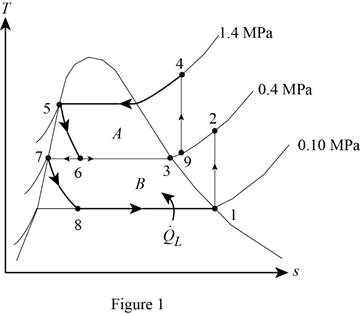
From Figure (1), write the specific enthalpy at state 5 is equal to state 6 due to throttling process.
Here, specific enthalpy at state 5 and 6 is
From Figure (1), write the specific enthalpy at state 7 is equal to state 8 due to throttling process.
Here, specific enthalpy at state 7 and 8 is
Express the fraction of the refrigerant that evaporates as it is throttled to the flash chamber
Here, specific enthalpy at saturated vapor is
Conclusion:
Perform unit conversion of pressure at state 1 from
Refer Table A-12, “saturated refrigerant-134a-pressure table”, and write the properties corresponding to pressure at state 1
Here, specific entropy and enthalpy at state 1 is
Refer Table A-13, “superheated refrigerant 134a”, and write the specific enthalpy at state 2 corresponding to pressure at state 2 of
Write the formula of interpolation method of two variables.
Here, the variables denote by x and y is specific entropy at state 2 and specific enthalpy at state 2 respectively.
Show the specific enthalpy at state 2 corresponding to specific entropy as in Table (1).
|
Specific entropy at state 2 |
Specific enthalpy at state 2 |
| 0.9306 | 256.59 |
| 0.9519 | |
| 0.9628 | 265.88 |
Substitute
Thus, the specific enthalpy at state 2 is,
Perform unit conversion of pressure at state 3 from
Refer Table A-12, “saturated refrigerant-134a-pressure table”, and write the property corresponding to pressure at state 3
Perform unit conversion of pressure at state 5 from
Refer Table A-12, “saturated refrigerant-134a-pressure table”, and write the property corresponding to pressure at state 5
Here, specific enthalpy at saturated liquid is
Substitute
Refer Table A-12, “saturated refrigerant-134a-pressure table”, and write the property corresponding to pressure at state 8
Substitute
Refer Table A-12, “saturated refrigerant-134a-pressure table”, and write the specific enthalpy at evaporation and pressure of
Substitute
Hence, the fraction of the refrigerant that evaporates as it is throttled to the flash chamber is
(b)
The rate of heat removed from the refrigerated space.
(b)
Answer to Problem 56P
The rate of heat removed from the refrigerated space is
Explanation of Solution
Express the enthalpy at state 9 by using an energy balance on the mixing chamber.
Here, the rate of total energy entering the system is
Express the mass flow rate through the flash chamber.
Here, mass flow rate through condenser is
Express The rate of heat removed from the refrigerated space.
Conclusion:
Substitute
Substitute
Substitute
Hence, the rate of heat removed from the refrigerated space is
(c)
The coefficient of performance.
(c)
Answer to Problem 56P
The coefficient of performance is
Explanation of Solution
Express compressor work input per unit mass.
Express the coefficient of performance.
Express entropy at state 4.
Here, specific entropy at state 3 is
Conclusion:
Refer Table A-12, “saturated refrigerant-134a-pressure table”, and write the property corresponding to pressure at state 3
Here, specific entropy at saturated vapor is
Substitute
Refer Table A-13, “superheated refrigerant 134a”, and write the specific enthalpy at state 4 corresponding to pressure at state 4 of
Show the specific enthalpy at state 4 corresponding to specific entropy as in Table (2).
|
Specific entropy at state 4 |
Specific enthalpy at state 4 |
| 0.9389 | 285.47 |
| 0.9436 | |
| 0.9733 | 297.10 |
Use excels and substitute value from Table (2) in Equation (IV) to get,
Substitute
Substitute
Hence, the coefficient of performance is
Want to see more full solutions like this?
Chapter 11 Solutions
THERMODYNAMICS: ENG APPROACH LOOSELEAF


- Water flows in a 2-ft-wide rectangular channel at a rate of 10 ft³/s. If the water depth downstream of a hydraulic jump is 2.5 ft, determine (a) the water depth upstream of the jump, (b) the upstream and (c) downstream Froude numbers, and (d) the head loss across the jump. (a) y₁ = i (b) Fr₁ = i (c) Fr₂ = i (d) h₁ = ft ftarrow_forwardA hydraulic jump at the base of a spillway of a dam is such that the depths upstream and downstream of the jump are 0.8 and 3.2 m, respectively (see the Video). If the spillway is 12 m wide, what is the flowrate over the spillway? Q= i m³/sarrow_forward(Manning equation) Water flows in a rectangular channel of width b at a depth of b/2. Determine the diameter of a circular channel (in terms of b) that carries the same flowrate when it is half-full. Both channels have the same Manning coefficient, n, and slope. barrow_forward
- (Manning equation) A weedy irrigation canal of trapezoidal cross section is to carry 20 m³/s when built on a slope of 0.60 m/km. If the sides are at a 45° angle and the bottom is 8 m wide, determine the width of the waterline at the free surface. i marrow_forwardWater flows in a 1.2-m-diameter finished concrete pipe so that it is completely full and the pressure is constant all along the pipe. If the slope is So = 0.0073, (a) determine the flowrate by using open-channel flow methods. Compare this result with (b) that obtained using the pipe flow methods of Chapter 8 (Use Colebrook formula, Table 8.1, Table 10.1 and assume that Re > 10º). (a) Q = i (b) Q = i m³/s m³/sarrow_forwardfor this 4 figuredarw the Kinematic Diagram:DoF:F=Type/Name ofmechanismEvolution:arrow_forward
- Two channels and two plates are used to formthe column section shown. For b = 200 mm,determine the moments of inertia and theradii of gyration of the combined section withrespect to the centroidal x and y axes.For the section of problem, determine thefirst moment of the upper plate about thecentroidal x-axisarrow_forwardDetermine by direct integration the moment of inertia of theshaded area at right with respect to the x axis shown. Determine by direct integration the moment of inertia of theshaded area of the figure with respect to the y axis shown.arrow_forwardFor the following MATLAB code, I need to answer a few questions. Can you identify the curves as elliptic functions? Which curves reflect the sn, cn, and dn functions?From the curves, determine the maximum amplitudes and the period corresponding toeach angular velocity component. clc; clear all; I = [500; 125; 425]; w = [0.2; 0.1; 0.2]; rev = 0:0.01:10; C = eye(3); % Using ode45 to integrate the KDE and DDE options = odeset('RelTol',1e-9,'AbsTol',1e-9); result = ode45(@K_DDE, rev, [w; I; C(:)], options); v = result.x; % Extracting information from the ode45 solver w = result.y(1:3, :); C_ode = reshape(result.y(7:end, :), [3,3,length(v)]); plot(v, w) xlabel('rev') ylabel('w (rad/s)') legend('w1', 'w2', 'w3') % Functions function dwCdt = K_DDE(~, w_IC) % Extracting the initial condtions to a variable w = w_IC(1:3); I = w_IC(4:6); C = reshape(w_IC(7:end), [3, 3]); I1 = I(1); I2 = I(2); I3 = I(3); K1 = -(I3-I2)/I1; K2 = -(I1-I3)/I2; K3 = -(I2-I1)/I3; %…arrow_forward
- please show a drawing/image and explain how to properly do the question. thanksarrow_forwardFor the four-bar- linkage shown in the following figure. BC=68mm, CD=100mm, AD=120mm. Determine the range of AB to make it a crank-rocker mechanism. B Darrow_forwardall of those 4 fi 1)Draw kinematic diagram: 2)DOF: 3)type/name of mechanism 4)evolution:arrow_forward
 Refrigeration and Air Conditioning Technology (Mi...Mechanical EngineeringISBN:9781305578296Author:John Tomczyk, Eugene Silberstein, Bill Whitman, Bill JohnsonPublisher:Cengage Learning