
Videos
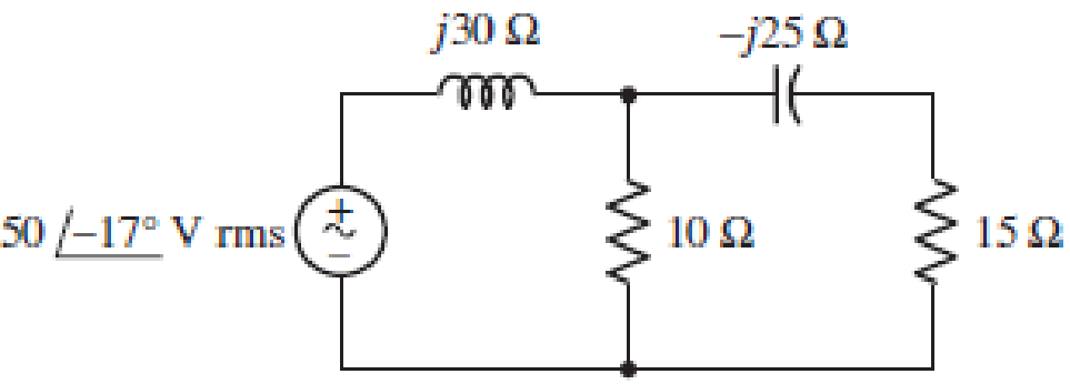
■ FIGURE 11.49
Instead of including a capacitor as indicated in Fig. 11.49, the circuit is erroneously constructed using two identical inductors, each having an impedance of j30 W at the operating frequency of 50 Hz. (a) Compute the complex power delivered to each passive component. (b) Verify your solution by calculating the complex power supplied by the source. (c) At what power factor is the source operating?
(a)
Find the complex power delivered to each passive element when
Answer to Problem 53E
The complex power delivered to
Explanation of Solution
Given data:
Refer to Figure 11.49 in the textbook for the given circuit.
Operating frequency is 50 Hz.
Formula used:
Write the expression for complex power delivered to the element as follows:
Here,
Write the expression for current in terms of voltage and impedance as follows:
Calculation:
Consider
Use the expression in Equation (2) and find the source current as follows:
Substitute
Use voltage division rule and find the voltage across
Substitute
Modify the expression in Equation (1) for the complex power delivered to
Substitute
Consider the node voltage across the shunt branches as
Substitute
Use current division rule and find the current through
Substitute
Modify the expression in Equation (1) for the complex power delivered to the
Substitute
Use voltage division rule and find the voltage across
Substitute
Use current division rule and find the current through
Substitute
Modify the expression in Equation (1) for the complex power delivered to the
Substitute
Use voltage division rule and find the voltage across
Substitute
Modify the expression in Equation (1) for the complex power delivered to the
Substitute
Conclusion:
Thus, the complex power delivered to
(b)
Verify the solution obtained in Part (a) by calculating the complex power supplied by the source.
Explanation of Solution
Calculation:
Modify the expression in Equation (1) for the complex power supplied by the source as follows:
Substitute
Write the expression for sum of complex delivered to (or absorbed by) each passive element as follows:
From Part (a), substitute
From the calculation, it is clear that, the complex power supplied by the source is equal to the complex power delivered to each passive element.
Conclusion:
Thus, the solution obtained in Part (a) is verified.
(c)
Find the power factor of the source.
Answer to Problem 53E
The power factor of the source is 0.253 lagging.
Explanation of Solution
Formula used:
Write the expression for complex power in the rectangular form as follows:
Here,
Write the expression for power factor as follows:
Calculation:
Rewrite the expression for complex power supplied by the source in rectangular form as follows:
Compare the complex power supplied by the source with the expression in Equation (3) and write the average and reactive power supplied by the source as follows:
Substitute 19.1482 W for
If the imaginary part of the complex power (reactive power) is positive value, then the load has lagging power factor. If the imaginary part is negative value, then the load has leading power factor.
As the imaginary part of the given complex power is positive value, the power factor is lagging power factor.
Conclusion:
Thus, the power factor of the source is 0.253 lagging.
Want to see more full solutions like this?
Chapter 11 Solutions
Loose Leaf for Engineering Circuit Analysis Format: Loose-leaf


- Q6)) The transistors in the feedback amplifier shown are identical, and their h-parameters are.. hie = 1.1k, hfe = 50, hre=o, and hoe = 0. Calculate Auf, Rif and Rof. {Ans: 6031583; 4. Kor. Is 4 4.7 k www 4.7k 91k 4.7k 91k 10k 1k. 10k 21000 4.7k w 15k Fig. 2.19 Circuit for Q6.arrow_forwardQ5 For the circuit shown in Fig. 2.18, hie =1.1 KQ, hfe =50. Find Avf, Rif and Rof Ans: -3.2; 193 ; 728 N. Vcc Vs Rs=10kQ Re=4KQ RF - = 40ΚΩ www Fig. 2.18 Circuit for Qs.arrow_forwardSheet No.2 Qi For the source follower shown in Fig. 2.14, Ipss =16 mA, V₂ =-4V, and VGsQ=-2.86 V. Find Avf, Rif and Rof. Assume rd is high. Ans: 0.833; ∞0; 365.7 . VDD Vo Vs R = 2.2 k Fig. 2.14 Circuit for Qi.arrow_forward
- Q4 For the circuit shown in Fig. 2.17, he-100, he -1KQ. Find A, A, R and Rof- Ans:-100; -5; 100 K; 250K. Voc RB = 100 k R.=5k Vs Rs 500 R. = 1 kn Fig. 2.17 Circuit for Quarrow_forwardQ3 The circuit of Fig. 2.16 is to have Af = -1 mA/V, D=1+ BA=50, a voltage gain of -4, Rs = 1KQ, and hfe = 150. Find RL, Re, Rif and Rof. Ans: 4 KN; 980 ; 150 KN; ∞. Vcc RL Vs -OV +11 Fig. 2.16 Circuit for Q3.arrow_forwardQ2 For the circuit shown in Fig. 2.15 hfe =150, hie =1KQ. Find Avf and Rif. Ans: 0.986; 152 KN. Vee R=4k2 Rs 1kQ Vo V, VR=1 KQ Fig. 2.15 Circuit for Q2-arrow_forward
- R1 is 978 ohms, R2 is 2150 ohms R3 is 4780 ohmsarrow_forwardPleasw draw the block diagram, don't type out what it could look like. Draw it. Thank youarrow_forward(Keynes model in continuous time) A continuous version of the Keynes modelis given by the equationsY= C + I + GT*(dC/dt) + C = aYT*(dI/dt) + I = b*(dC/dt)Write the equations in state space form, and give the conditions for stability.arrow_forward
- Can the expert solve an Integral In detall? ⑥M-1 大 80*10万 1012 es dw 7010 80x10³ ⒸP= 1 Sin (Iwl+1) dw 70x10xarrow_forwardQ1:A) Draw the directional control of DC motor using a relay. Switch controlled by PLC +V Ov (a) Motor OV (b) Motor 10 B) Define the encoder with mention its types. The term encoder is used for a device that provides a digital output as a result of angular or linear displacement. incremental encoder 2 6 absolute encoder 2 10 Q2: A) Suppose that PLC connected to three pushbutton switches as shown in this illustration: 4 2000000 0000 000000 0000 Draw a Ladder Diagram program for PLC to turn the lamp ON when the switch statuses be: Switch A = pressed, Switch B = pressed, Switch C = pressed 1:0 I:0 I:0 0:0 H/HH/H 2 Managemenarrow_forwardExample2:- 8. = e.A nia +2.1 = Find the maximum steady-state power capability of a system consisting of a generator equivalent reactance of 0.4pu connected to an infinite bus through a series reactance of 1.0 p.u. The terminal voltage of the generator is held at1.10 p.u. and the voltage of the infinite bus is 1.0 p.u.arrow_forward
 Introductory Circuit Analysis (13th Edition)Electrical EngineeringISBN:9780133923605Author:Robert L. BoylestadPublisher:PEARSON
 Delmar's Standard Textbook Of ElectricityElectrical EngineeringISBN:9781337900348Author:Stephen L. HermanPublisher:Cengage Learning
 Programmable Logic ControllersElectrical EngineeringISBN:9780073373843Author:Frank D. PetruzellaPublisher:McGraw-Hill Education
 Fundamentals of Electric CircuitsElectrical EngineeringISBN:9780078028229Author:Charles K Alexander, Matthew SadikuPublisher:McGraw-Hill Education
 Electric Circuits. (11th Edition)Electrical EngineeringISBN:9780134746968Author:James W. Nilsson, Susan RiedelPublisher:PEARSON
 Engineering ElectromagneticsElectrical EngineeringISBN:9780078028151Author:Hayt, William H. (william Hart), Jr, BUCK, John A.Publisher:Mcgraw-hill Education,