
Concept explainers
Videos
The diagram below shows a ruler balanced with the fulcrum at the 50-cm mark. Copy the diagram onto a sheet of paper and answer Questions 50-52 below.
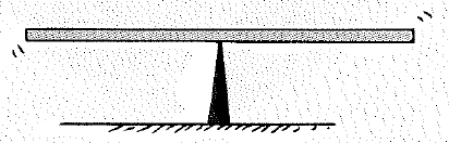
If a 200-g mass is placed at the 20-cm mark (30 cm from the fulcrum), at what mark should a 500-g mass be placed So that the system balances?
To calculate: The marking distance where the mass 500g is placed to balancing the system.
Answer to Problem 50A
The marking distance where the mass 500g is placed to balancing the system is 62cm.
Explanation of Solution
Given:
The mass is 200gm which is placed at the distance of 20cm and 30cm from the fulcrum and another mass is 500gm.
Formula used:
According to the principle of moments in equilibrium,
Calculation:
Consider the figure shown below.
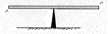
On the bases of given figure, the fulcrum is at 50cm and according to the principle of moments, the vector sum of moment of the forces acting on the rigid body when a rigid body is in rotational equilibrium. Therefore, the summing moments about this 50cm mark for balancing the system. Take the clockwise moments as positive and anticlockwise moments as negative. So, the distance is,
Therefore, the mark will be 50cm plus calculated distance. So, the marking distance is
Conclusion:
Thus, the distance is 62cm.
Chapter 11 Solutions
Conceptual Physics C2009 Guided Reading & Study Workbook Se
Additional Science Textbook Solutions
Campbell Biology (11th Edition)
Organic Chemistry (8th Edition)
Human Physiology: An Integrated Approach (8th Edition)
Human Biology: Concepts and Current Issues (8th Edition)
Genetic Analysis: An Integrated Approach (3rd Edition)
Chemistry: Structure and Properties (2nd Edition)


- Kirchoff's Laws. A circuit contains 3 known resistors, 2 known batteries, and 3 unknown currents as shown. Assume the current flows through the circuit as shown (this is our initial guess, the actual currents may be reverse). Use the sign convention that a potential drop is negative and a potential gain is positive. E₂ = 8V R₁₁ = 50 R₂ = 80 b с w 11 www 12 13 E₁ = 6V R3 = 20 a) Apply Kirchoff's Loop Rule around loop abefa in the clockwise direction starting at point a. (2 pt). b) Apply Kirchoff's Loop Rule around loop bcdeb in the clockwise direction starting at point b. (2 pt). c) Apply Kirchoff's Junction Rule at junction b (1 pt). d) Solve the above 3 equations for the unknown currents I1, 12, and 13 and specify the direction of the current around each loop. (5 pts) I1 = A 12 = A 13 = A Direction of current around loop abef Direction of current around loop bcde (CW or CCW) (CW or CCW)arrow_forwardNo chatgpt pls will upvotearrow_forward4.) The diagram shows the electric field lines of a positively charged conducting sphere of radius R and charge Q. A B Points A and B are located on the same field line. A proton is placed at A and released from rest. The magnitude of the work done by the electric field in moving the proton from A to B is 1.7×10⁻¹⁶ J. Point A is at a distance of 5.0×10⁻²m from the centre of the sphere. Point B is at a distance of 1.0×10⁻¹ m from the centre of the sphere. (a) Explain why the electric potential decreases from A to B. [2] (b) Draw, on the axes, the variation of electric potential V with distance r from the centre of the sphere. R [2] (c(i)) Calculate the electric potential difference between points A and B. [1] (c(ii)) Determine the charge Q of the sphere. [2] (d) The concept of potential is also used in the context of gravitational fields. Suggest why scientists developed a common terminology to describe different types of fields. [1]arrow_forward
- 3.) The graph shows how current I varies with potential difference V across a component X. 904 80- 70- 60- 50- I/MA 40- 30- 20- 10- 0+ 0 0.5 1.0 1.5 2.0 2.5 3.0 3.5 4.0 4.5 5.0 VIV Component X and a cell of negligible internal resistance are placed in a circuit. A variable resistor R is connected in series with component X. The ammeter reads 20mA. 4.0V 4.0V Component X and the cell are now placed in a potential divider circuit. (a) Outline why component X is considered non-ohmic. [1] (b(i)) Determine the resistance of the variable resistor. [3] (b(ii)) Calculate the power dissipated in the circuit. [1] (c(i)) State the range of current that the ammeter can measure as the slider S of the potential divider is moved from Q to P. [1] (c(ii)) Describe, by reference to your answer for (c)(i), the advantage of the potential divider arrangement over the arrangement in (b).arrow_forward1.) Two long parallel current-carrying wires P and Q are separated by 0.10 m. The current in wire P is 5.0 A. The magnetic force on a length of 0.50 m of wire P due to the current in wire Q is 2.0 × 10-s N. (a) State and explain the magnitude of the force on a length of 0.50 m of wire Q due to the current in P. [2] (b) Calculate the current in wire Q. [2] (c) Another current-carrying wire R is placed parallel to wires P and Q and halfway between them as shown. wire P wire R wire Q 0.05 m 0.05 m The net magnetic force on wire Q is now zero. (c.i) State the direction of the current in R, relative to the current in P.[1] (c.ii) Deduce the current in R. [2]arrow_forward2.) A 50.0 resistor is connected to a cell of emf 3.00 V. The voltmeter and the ammeter in the circuit are ideal. V A 50.00 (a) The current in the ammeter is 59.0 mA. Calculate the internal resistance of the cell. The circuit is changed by connecting another resistor R in parallel to the 50.0 resistor. V A 50.00 R (b) Explain the effect of this change on R is made of a resistive wire of uniform cross-sectional area 3.1 × 10⁻⁸ m², resistivity 4.9 × 10-70m and length L. The resistance of R is given by the equation R = KL where k is a constant. (b.i) the reading of the ammeter. [2] (b.ii) the reading of the voltmeter. [2] (c) Calculate k. State an appropriate unit for your answer. [3] [2]arrow_forward
- No chatgpt pls will upvotearrow_forwardNo chatgpt pls will upvotearrow_forwardA rod 12.0 cm long is uniformly charged and has a total charge of -20.0 μc. Determine the magnitude and direction of the electric field along the axis of the rod at a point 32.0 cm from its center. 361000 ☑ magnitude What is the general expression for the electric field along the axis of a uniform rod? N/C direction toward the rodarrow_forward
 College PhysicsPhysicsISBN:9781305952300Author:Raymond A. Serway, Chris VuillePublisher:Cengage Learning
 University Physics (14th Edition)PhysicsISBN:9780133969290Author:Hugh D. Young, Roger A. FreedmanPublisher:PEARSON
 Introduction To Quantum MechanicsPhysicsISBN:9781107189638Author:Griffiths, David J., Schroeter, Darrell F.Publisher:Cambridge University Press
 Physics for Scientists and EngineersPhysicsISBN:9781337553278Author:Raymond A. Serway, John W. JewettPublisher:Cengage Learning
 Lecture- Tutorials for Introductory AstronomyPhysicsISBN:9780321820464Author:Edward E. Prather, Tim P. Slater, Jeff P. Adams, Gina BrissendenPublisher:Addison-Wesley
 College Physics: A Strategic Approach (4th Editio...PhysicsISBN:9780134609034Author:Randall D. Knight (Professor Emeritus), Brian Jones, Stuart FieldPublisher:PEARSON