
Videos
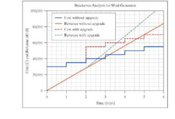
When a wine generator is installed there is a substantial initial cost, but daily operation requires no further cash payment. However, to keep the generator in proper operating condition, it must undergo maintenance once a year. Each maintenance cycle requires a cash payment of $5000. The solid lines on the following graph show this situation. The stepped blue line shows the cost over time and the straight brown line shows the revenue derived from the generator.
As the second yearly maintenance approaches, you are informed by the manufacturer that a significant upgrade is available for additional cost. The upgrade will make the generator far more efficient, thus the revenue would increase substantially. The yearly maintenance cost after the upgrade would still be $5000. The dashed lines show the cost and revenue projections if the upgrade s installed.
- a. What is the amount of revenue per year without the upgrade?
- b. What is the initial cost of the wind generator?
- c. How many years after the initial installation do you break even if the upgrade is installed? List your answer as number of years 1 number of months.
- d. What is the cost of the upgrade completed at the two-year maintenance cycle? Note that this amount includes the standard $5000 maintenance fee.
- e. How many years after the initial installation would the profit be the same whether you upgrade or not? List your answer as number of years + number of months.
- f. How many years after the initial installation will you have made a profit of $25,000 if the upgrade is NOT installed? List your answer as number of years + number of months.
- g. If the upgrade results in increased reliability, thus increasing the maintenance interval to two years, though still at a cost of $5000 per maintenance, how many years after the initial installation v/ill you break even after the upgrade? List your answer as number of years + number of months.
Want to see the full answer?
Check out a sample textbook solution
Chapter 11 Solutions
Thinking Like an Engineer: An Active Learning Approach (4th Edition)
Additional Engineering Textbook Solutions
Mechanics of Materials (10th Edition)
Web Development and Design Foundations with HTML5 (8th Edition)
Automotive Technology: Principles, Diagnosis, And Service (6th Edition) (halderman Automotive Series)
Thermodynamics: An Engineering Approach
Java: An Introduction to Problem Solving and Programming (8th Edition)
Starting Out with Programming Logic and Design (5th Edition) (What's New in Computer Science)


- practise questionarrow_forwardCan you provide steps and an explaination on how the height value to calculate the Pressure at point B is (-5-3.5) and the solution is 86.4kPa.arrow_forwardPROBLEM 3.46 The solid cylindrical rod BC of length L = 600 mm is attached to the rigid lever AB of length a = 380 mm and to the support at C. When a 500 N force P is applied at A, design specifications require that the displacement of A not exceed 25 mm when a 500 N force P is applied at A For the material indicated determine the required diameter of the rod. Aluminium: Tall = 65 MPa, G = 27 GPa. Aarrow_forward
- Find the equivalent mass of the rocker arm assembly with respect to the x coordinate. k₁ mi m2 k₁arrow_forward2. Figure below shows a U-tube manometer open at both ends and containing a column of liquid mercury of length l and specific weight y. Considering a small displacement x of the manometer meniscus from its equilibrium position (or datum), determine the equivalent spring constant associated with the restoring force. Datum Area, Aarrow_forward1. The consequences of a head-on collision of two automobiles can be studied by considering the impact of the automobile on a barrier, as shown in figure below. Construct a mathematical model (i.e., draw the diagram) by considering the masses of the automobile body, engine, transmission, and suspension and the elasticity of the bumpers, radiator, sheet metal body, driveline, and engine mounts.arrow_forward
- 3.) 15.40 – Collar B moves up at constant velocity vB = 1.5 m/s. Rod AB has length = 1.2 m. The incline is at angle = 25°. Compute an expression for the angular velocity of rod AB, ė and the velocity of end A of the rod (✓✓) as a function of v₂,1,0,0. Then compute numerical answers for ȧ & y_ with 0 = 50°.arrow_forward2.) 15.12 The assembly shown consists of the straight rod ABC which passes through and is welded to the grectangular plate DEFH. The assembly rotates about the axis AC with a constant angular velocity of 9 rad/s. Knowing that the motion when viewed from C is counterclockwise, determine the velocity and acceleration of corner F.arrow_forward500 Q3: The attachment shown in Fig.3 is made of 1040 HR. The static force is 30 kN. Specify the weldment (give the pattern, electrode number, type of weld, length of weld, and leg size). Fig. 3 All dimension in mm 30 kN 100 (10 Marks)arrow_forward
- (read image) (answer given)arrow_forwardA cylinder and a disk are used as pulleys, as shown in the figure. Using the data given in the figure, if a body of mass m = 3 kg is released from rest after falling a height h 1.5 m, find: a) The velocity of the body. b) The angular velocity of the disk. c) The number of revolutions the cylinder has made. T₁ F Rd = 0.2 m md = 2 kg T T₂1 Rc = 0.4 m mc = 5 kg ☐ m = 3 kgarrow_forward(read image) (answer given)arrow_forward
 Elements Of ElectromagneticsMechanical EngineeringISBN:9780190698614Author:Sadiku, Matthew N. O.Publisher:Oxford University Press
 Mechanics of Materials (10th Edition)Mechanical EngineeringISBN:9780134319650Author:Russell C. HibbelerPublisher:PEARSON
 Thermodynamics: An Engineering ApproachMechanical EngineeringISBN:9781259822674Author:Yunus A. Cengel Dr., Michael A. BolesPublisher:McGraw-Hill Education
 Control Systems EngineeringMechanical EngineeringISBN:9781118170519Author:Norman S. NisePublisher:WILEY
 Mechanics of Materials (MindTap Course List)Mechanical EngineeringISBN:9781337093347Author:Barry J. Goodno, James M. GerePublisher:Cengage Learning
 Engineering Mechanics: StaticsMechanical EngineeringISBN:9781118807330Author:James L. Meriam, L. G. Kraige, J. N. BoltonPublisher:WILEY