
Videos
For the electromagnet in Fig. 11.75:
a. Find the flux density in Wb/m2.
b. What is the flux density in teslas?
c. What is the applied magnetmotive force?
d. What would the reading of the meter in Fig. 11.14 read in gauss?
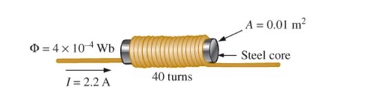
Fig. 11.75
(a)
The value of flux density.
Answer to Problem 1P
The value of flux density is
Explanation of Solution
Concept used:
Write the expression for magnetic flux density:
Here,
Calculation:
Substitute
Conclusion:
Thus,value of flux density is
(b)
The flux density in tesla.
Answer to Problem 1P
The value of flux density in tesla is
Explanation of Solution
Concept used:
Calculation:
The value of flux density
Conclusion:
Thus, value of flux density in tesla is
(c)
The value of applied magnetomotive force.
Answer to Problem 1P
The value of applied magnetomotive force is
Explanation of Solution
Concept used:
Write the expression for magnetomotive force.
Here,
Calculation:
Substitute
Conclusion:
Thus,value of applied magnetomotive force is
(d)
The value of flux density in gauss.
Answer to Problem 1P
The value of flux density in gauss is
Explanation of Solution
Concept used:
Calculation:
The value of flux density
Conclusion:
Thus, the value of flux density in gauss is
Want to see more full solutions like this?
Chapter 11 Solutions
Introductory Circuit Analysis (13th Edition)


- Describe the principle of operation of a lin- ear induction motor.arrow_forwardName the principal components of an in- duction motor. Explain how a revolving field is set up in a 3-phase induction motor.arrow_forwardAnswer all the questions (a) How much power is the wind farm generating? (b) How much power is the solar farm generating? (c) Find the power delivered to the AC motor. (d) If the AC motor requires at least 45 kW of power, is the system able to provide that power? If not, how many additional series PV modules should be added to each string (we want to keep the same number of modules in each string)? If so, how many modules can be removed from each string while still meeting the requirements?arrow_forward
- An open-circuit voltage of 240 V appears across the slip-rings of a wound-rotor in- duction motor when the rotor is locked. The stator has 6 poles and is excited by a 60 Hz source. If the rotor is driven by a variable-speed dc motor, calculate the open-circuit voltage and frequency across the slip-rings if the dc motor turns a. At 600 r/min, in the same direction as the rotating field b. At 900 r/min, in the same direction as the rotating field c. At 3600 r/min, opposite to the rotating fieldarrow_forwardIf we double the number of poles on the stator of an induction motor, will its syn- chronous speed also double? The rotor of an induction should never be locked while full voltage is being applied to the stator. Explain. Why does the rotor of an induction motor turn slower than the revolving field?arrow_forwarda. Calculate the synchronous speed of a 3-phase, 12-pole induction motor that is excited by a 60 Hz source. b. What is the nominal speed if the slip at full-load is 6 percent?arrow_forward
- A 3-phase, 75 hp, 440 V induction motor has a full-load efficiency of 91 percent and a power factor of 83 percent. Calculate the nominal current per phase.arrow_forwardPlease answer all the questions a) What is the minimum required transformer rating for each transformer in kVA? b) Find the voltage required at Bus 1. c) The loadcentre is to be powered by PV panels that have the same I-V curve (ISC = 120 A, VOC = 60 V). Identify the configuration that uses the minimum number of panels to provide enough power to Bus 1. You can assume that the inverter converts the power at 95% efficiency and requires V DC input to generate the same VRMS AC output.arrow_forwardWhat happens to the rotor speed and rotor current when the mechanical load on an in- duction motor increases? Would you recommend using a 50 hp in- duction motor to drive a 10 hp load? Explain. Give two advantages of a wound-rotor mo- tor over a squirrel-cage motor. Both the voltage and frequency induced in the rotor of an induction motor decrease as the rotor speeds up. Explain.arrow_forward
- Please provide explainations and detailed working. thank youarrow_forwardPlease provide explainations and detailed working. thank youarrow_forwardThe excitation of a three-phase synchronous motor connected in parallel with a load of 500 kW operating at 0-85 p.f. lagging is adjusted to improve the overall p.f. of the system to 0.95 lagging. If the mechanical load on the motor is 120 kW, calculate the kVA input to the synchronous motor and its p.f.?arrow_forward
 Introductory Circuit Analysis (13th Edition)Electrical EngineeringISBN:9780133923605Author:Robert L. BoylestadPublisher:PEARSON
 Delmar's Standard Textbook Of ElectricityElectrical EngineeringISBN:9781337900348Author:Stephen L. HermanPublisher:Cengage Learning
 Programmable Logic ControllersElectrical EngineeringISBN:9780073373843Author:Frank D. PetruzellaPublisher:McGraw-Hill Education
 Fundamentals of Electric CircuitsElectrical EngineeringISBN:9780078028229Author:Charles K Alexander, Matthew SadikuPublisher:McGraw-Hill Education
 Electric Circuits. (11th Edition)Electrical EngineeringISBN:9780134746968Author:James W. Nilsson, Susan RiedelPublisher:PEARSON
 Engineering ElectromagneticsElectrical EngineeringISBN:9780078028151Author:Hayt, William H. (william Hart), Jr, BUCK, John A.Publisher:Mcgraw-hill Education,