
Laboratory Manual for Introductory Circuit Analysis
13th Edition
ISBN: 9780133923780
Author: Robert L. Boylestad, Gabriel Kousourou
Publisher: PEARSON
expand_more
expand_more
format_list_bulleted
Videos
Textbook Question
Chapter 11, Problem 12P
For the circuit in Fig. 11.79 composed of standard values:
a. Determine T
b. Write the mathematical expression for the current iL after the switch is closed at
c. Write the mathematical expression for VL and VR after the switch is closed at
d. Determine iL and VL at
e. Sketch the waveforms of iL, vL. and VR for the storage phase.
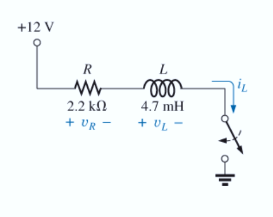
Fig. 11.79
Expert Solution & Answer
Want to see the full answer?
Check out a sample textbook solution
Students have asked these similar questions
Pls show neat and whole solution
I need help with this problem and an explanation of the solution for the image described below. (Introduction to Signals and Systems)
I need help with this problem and an explanation of the solution for the image described below. (Introduction to Signals and Systems)
Chapter 11 Solutions
Laboratory Manual for Introductory Circuit Analysis
Ch. 11 - For the electromagnet in Fig. 11.75: a. Find the...Ch. 11 - For the inductor in Fig. 11.76, find the...Ch. 11 - a. Repeat Problem 2 with a ferromagnetic core with...Ch. 11 - For the inductor in Fig. 11.77, find the...Ch. 11 - An air-core inductor has a total inductance of 4.7...Ch. 11 - What are the inductance and the range of expected...Ch. 11 - If the flux linking a coil of 50 turns changes at...Ch. 11 - Determine the rate of change of flux linking a...Ch. 11 - How many turns does a coil have if 42 mV are...Ch. 11 - Find the voltage induced across a coil of 22 mH if...
Ch. 11 - For the circuit of Fig. 11.78 composed of standard...Ch. 11 - For the circuit in Fig. 11.79 composed of standard...Ch. 11 - For the network of Fig. 11.80. a. Write the...Ch. 11 - Give a supply of 18 V, use standard values to...Ch. 11 - For the circuit in Fig. 11.82: a. Write the...Ch. 11 - In this problem, the effect of reversing the...Ch. 11 - For the network of Fig. 11.84: a. Find the...Ch. 11 - Prob. 18PCh. 11 - Prob. 19PCh. 11 - Prob. 20PCh. 11 - For the network in Fig. 11.88: a. Determine the...Ch. 11 - For the network in Fig. 11.89: a. Write the...Ch. 11 - Prob. 23PCh. 11 - For Fig. 11.91: a. Determine the mathematical...Ch. 11 - For Fig. 11.92: a. Determine the mathematical...Ch. 11 - For the network in Fig. 11.93, the switch is...Ch. 11 - The switch in Fig. 11.94 has been open for a long...Ch. 11 - Prob. 28PCh. 11 - The switch for the network in Fig. 11.96 has been...Ch. 11 - The switch in Fig. 11.97 has been closed for a...Ch. 11 - Given iL=100mA(1e-t/20ms) a. Determine iLatt=1ms....Ch. 11 - a. If the measured current for an inductor during...Ch. 11 - The network in Fig. 11.98 employs a DMM with an...Ch. 11 - Find the waveform for the voltage induced across a...Ch. 11 - Find the waveform for the voltage induced across a...Ch. 11 - Prob. 36PCh. 11 - Find the total inductance of the circuit of Fig....Ch. 11 - Find the total inductance for the network of Fig....Ch. 11 - Reduce the network in Fig. 11.104 to the fewest...Ch. 11 - Reduce the network in Fig. 11.105 to the fewest...Ch. 11 - Reduce the network of Fig. 11.106 to the fewest...Ch. 11 - For the network in Fig. 11.107: a. Write the...Ch. 11 - For the network in Fig. 11.108: a. Write the...Ch. 11 - For the network in Fig. 11.109. a. Find the...Ch. 11 - Find the steady-state currents I1 and I2 for the...Ch. 11 - Find the steady-state currents and voltages for...Ch. 11 - Find the steady-state currents and voltages for...Ch. 11 - Find the indicated steady-state currents and...Ch. 11 - Prob. 49PCh. 11 - Using PSpice or Multisim, verify the results of...Ch. 11 - Using the PSpice or Multisim, find the solution to...Ch. 11 - Using PSpice or Multisim, find the solution to...Ch. 11 - Using PSpice or Multisim, verify the results of...
Knowledge Booster


Learn more about
Need a deep-dive on the concept behind this application? Look no further. Learn more about this topic, electrical-engineering and related others by exploring similar questions and additional content below.Similar questions
- The input signal in the op-amp circuit of Fig. P7.80 is given by uin(t) =V0 coswt. Assuming the op amp is operating within its linear range, obtain an expression for your(t) by applying the phasor-domain technique and then evaluate it for wRC = 1.arrow_forwardFor ui(t)=V0 coswt, obtain an expression for uout(t) in thecircuit of Fig. P7.82 and then evaluate it for V0 = 4 V, w = 400rad/s, R = 5 kW, and C = 2.5 μF.arrow_forwardCan you help me to solve the question?arrow_forward
- The input signal in the op-amp circuit of Fig. P7.81 is givenbyuin(t) = 0.5cos2000t V.Obtain an expression for uout(t) and then evaluate it forR1 = 2 kW, R2 = 10 kW, and C = 0.1 μF.arrow_forwardHANDWRITTEN SOLUTION REQUIRED NOT USING CHATGPTarrow_forwardFundamentals of Energy Systems HW 2 Q2arrow_forward
arrow_back_ios
SEE MORE QUESTIONS
arrow_forward_ios
Recommended textbooks for you
 Electricity for Refrigeration, Heating, and Air C...Mechanical EngineeringISBN:9781337399128Author:Russell E. SmithPublisher:Cengage Learning
 Delmar's Standard Textbook Of ElectricityElectrical EngineeringISBN:9781337900348Author:Stephen L. HermanPublisher:Cengage Learning
Electricity for Refrigeration, Heating, and Air C...
Mechanical Engineering
ISBN:9781337399128
Author:Russell E. Smith
Publisher:Cengage Learning
Delmar's Standard Textbook Of Electricity
Electrical Engineering
ISBN:9781337900348
Author:Stephen L. Herman
Publisher:Cengage Learning
Inductors Explained - The basics how inductors work working principle; Author: The Engineering Mindset;https://www.youtube.com/watch?v=KSylo01n5FY;License: Standard Youtube License