
Bundle: Mechanics Of Materials, Loose-leaf Version, 9th + Mindtap Engineering, 1 Term (6 Months) Printed Access Card
9th Edition
ISBN: 9781337594318
Author: Barry J. Goodno; James M. Gere
Publisher: Cengage Learning
expand_more
expand_more
format_list_bulleted
Concept explainers
Videos
Textbook Question
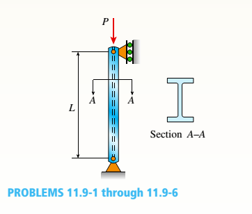
Chapter 11, Problem 11.9.1P
Determine the allowable axial load Pallowa W 10 X 45 steel wide-flange column with pinned ends (see figure) for each of the following lengths: L = 8 ft, 16 ft, 24 ft, and 32 ft. (Assume E = 29,000 ksi and
Expert Solution & Answer

Trending nowThis is a popular solution!

Students have asked these similar questions
I need a mechanical engineering expert to solve this question,no Ai please
Can you give me the meaning of Combination spanner and Give Examples of Spanners
HW8
A shaft fitted with a flywheel rotates at 650 r.p.m. and drives a machine. The
torque of machine varies in a cyclic manner over a period of 2 revolutions. The
torque rises from 650 N-m to 2200 N-m uniformly during 110° and remains
constant for the following 270°. It then falls uniformly to 600 N-m during the next
100° and remains constant for the end cycle, the cycle being repeated thereafter.
Determine the power required to drive the machine and percentage fluctuation in
speed, if the driving torque applied to the shaft is constant and the mass of the
flywheel is 180 kg with radius of gyration of 35 cm.
HW9
Chapter 11 Solutions
Bundle: Mechanics Of Materials, Loose-leaf Version, 9th + Mindtap Engineering, 1 Term (6 Months) Printed Access Card
Ch. 11 - A rigid bar of length L is supported by a linear...Ch. 11 - The figure shows an idealized structure consisting...Ch. 11 - -2-3. Two rigid bars are connected with a...Ch. 11 - Repeat Problem 11.2-3 assuming that R= 10 kN ·...Ch. 11 - The figure shows an idealized structure consisting...Ch. 11 - An idealized column consists of rigid bar ABCD...Ch. 11 - An idealized column is made up of rigid segments...Ch. 11 - The figure shows an idealized structure consisting...Ch. 11 - The figure shows an idealized structure consisting...Ch. 11 - The figure shows an idealized structure consisting...
Ch. 11 - The figure shows an idealized structure consisting...Ch. 11 - Rigid column ABCD has an elastic support at B with...Ch. 11 - An idealized column is made up of rigid bars ABC...Ch. 11 - An idealized column is composed of rigid bars ABC...Ch. 11 - Repeat Problem 11.2-14 using L = 12 ft, ß = 0.25...Ch. 11 - An idealized column is composed of rigid bars ABC...Ch. 11 - Column AB has a pin support at A,a roller support...Ch. 11 - Slender column ABC is supported at A and C and is...Ch. 11 - Calculate the critical load PCTfor a W 8 × 35...Ch. 11 - Solve the preceding problem for a W 250 × 89 steel...Ch. 11 - Solve Problem 11.3-3 for a W 10 × 45 steel column...Ch. 11 - A horizontal beam AB is pin-supported at end A and...Ch. 11 - A column ABC is supported at ends A and C and...Ch. 11 - Find the controlling buckling load (kN) for the...Ch. 11 - A column, pinned at top and bottom, is made up of...Ch. 11 - Repeat Problem 11.3-9. Use two C 150 × 12.2 steel...Ch. 11 - A horizontal beam AB is pin-supported at end A and...Ch. 11 - -12 A horizontal beam AB is supported at end A and...Ch. 11 - A horizontal beam AB has a sliding support at end...Ch. 11 - A slender bar AB with pinned ends and length L is...Ch. 11 - A rectangular column with cross-sectional...Ch. 11 - .16 Three identical, solid circular rods, each of...Ch. 11 - Three pinned-end columns of the same material have...Ch. 11 - A long slender column ABC is pinned at ends A and...Ch. 11 - The roof over a concourse at an airport is...Ch. 11 - The hoisting arrangement for lifting a large pipe...Ch. 11 - A pinned-end strut of aluminum (E = 10,400 ksi)...Ch. 11 - The cross section of a column built up of two...Ch. 11 - The truss ABC shown in the figure supports a...Ch. 11 - A truss ABC supports a load W at joint B, as shown...Ch. 11 - An S6 × 12.5 steel cantilever beam AB is supported...Ch. 11 - The plane truss shown in the figure supports...Ch. 11 - A space truss is restrained at joints O, A,B, and...Ch. 11 - A fixed-end column with circular cross section is...Ch. 11 - A cantilever aluminum column has a square tube...Ch. 11 - An aluminum pipe column (E = 10,400 ksi) with a...Ch. 11 - Solve the preceding problem for a steel pipe...Ch. 11 - A wide-flange steel column (E = 30 × l06 psi) of...Ch. 11 - Prob. 11.4.6PCh. 11 - The upper end of a WE × 21 wide-flange steel...Ch. 11 - A vertical post AB is embedded in a concrete...Ch. 11 - The horizontal beam ABC shown in the figure is...Ch. 11 - The roof beams of a warehouse are supported by...Ch. 11 - Determine the critical load Pcrand the equation of...Ch. 11 - A fixed-pinned column is a W310 × 21 steel shape...Ch. 11 - Find the Controlling buckling load (kips) for the...Ch. 11 - Prob. 11.4.14PCh. 11 - A rigid L-shaped frame is supported by a steel...Ch. 11 - An aluminum tube AB with a circular cross section...Ch. 11 - The frame ABC consists of two members AB and BC...Ch. 11 - An aluminum bar having a rectangular cross section...Ch. 11 - ‘11.5-2 A steel bar having a square cross section...Ch. 11 - A simply supported slender column is subjected to...Ch. 11 - A brass bar of a length L = 0.4 m is loaded at end...Ch. 11 - Determine the bending moment M in the pinned-end...Ch. 11 - Plot the load-deflection diagram for a pinned-end...Ch. 11 - Solve the preceding problem for a column with e =...Ch. 11 - A wide-flange member (W200 × 22.5) is compressed...Ch. 11 - A wide-f hinge member (W 10 × 30) is compressed by...Ch. 11 - Solve the preceding problem (W 250 × 44.8) if the...Ch. 11 - The column shown in the figure is fixed at the...Ch. 11 - An aluminum box column with a square cross section...Ch. 11 - Solve the preceding problem for an aluminum column...Ch. 11 - A steel post /t if with a hollow circular cross...Ch. 11 - A frame ABCD is constructed of steel wide-flange...Ch. 11 - A steel bar has a square cross section of width b...Ch. 11 - ]11.6-2 A brass bar (E = 100 GPa) with a square...Ch. 11 - A square aluminum bar with pinned ends carries a...Ch. 11 - A pinned-and column of a length L = 2A m is...Ch. 11 - A pinned-end strut of a length L = 5.2 ft is...Ch. 11 - A circular aluminum tube with pinned ends supports...Ch. 11 - A steel W 12 × 35 column is pin-supported at the...Ch. 11 - A steel W 310 x 52 column is pin-supported at the...Ch. 11 - A steel column (E = 30 x 103 ksi) with pinned ends...Ch. 11 - A W410 × S5 steel column is compressed by a force...Ch. 11 - A steel column ( E = 30 X 103 ksi) that is fixed...Ch. 11 - AW310 × 74 wide-flange steel column with length L...Ch. 11 - A pinned-end column with a length L = 18 ft is...Ch. 11 - The wide-flange, pinned-end column shown in the...Ch. 11 - A W14 × 53 wide-flange column of a length L = 15...Ch. 11 - A wide-flange column with a bracket is fixed at...Ch. 11 - Determine the allowable axial load Pallowa W 10 X...Ch. 11 - Determine the allowable axial load Pallowfor a W...Ch. 11 - Determine the allowable axial load Pallowfor a W...Ch. 11 - Select a steel wide-flange column of a nominal...Ch. 11 - Prob. 11.9.5PCh. 11 - Select a steel wide-flange column of a nominal...Ch. 11 - Prob. 11.9.7PCh. 11 - Determine the allowable axial load Pallowfor a...Ch. 11 - Determine the allowable axial load Pallowfor a...Ch. 11 - Determine the allowable axial load Pallowfor a...Ch. 11 - -11 Determine the maximum permissible length...Ch. 11 - Determine the maximum permissible length Lmaxfor a...Ch. 11 - A steel pipe column with pinned ends supports an...Ch. 11 - The steel columns used in a college recreation...Ch. 11 - A W8 × 28 steel wide-flange column with pinned...Ch. 11 - Prob. 11.9.16PCh. 11 - Prob. 11.9.17PCh. 11 - Prob. 11.9.18PCh. 11 - Prob. 11.9.19PCh. 11 - Prob. 11.9.20PCh. 11 - Prob. 11.9.21PCh. 11 - An aluminum pipe column (alloy 2014-T6) with...Ch. 11 - Prob. 11.9.23PCh. 11 - Prob. 11.9.24PCh. 11 - Prob. 11.9.25PCh. 11 - Prob. 11.9.26PCh. 11 - Prob. 11.9.27PCh. 11 - Prob. 11.9.28PCh. 11 - Prob. 11.9.29PCh. 11 - Prob. 11.9.30PCh. 11 - A wood column with, a rectangular cross section...Ch. 11 - Prob. 11.9.32PCh. 11 - Prob. 11.9.33PCh. 11 - A square wood column with side dimensions b (see...Ch. 11 - A square wood column with side dimensions b (see...Ch. 11 - Prob. 11.9.36P
Knowledge Booster


Learn more about
Need a deep-dive on the concept behind this application? Look no further. Learn more about this topic, mechanical-engineering and related others by exploring similar questions and additional content below.Similar questions
- units of h. show all workarrow_forward4. Steam flows steadily through a turbine at a rate of 47,000 lbm/h, entering at 1000 psia and 800°F and leaving at 6 psia as saturated vapor. If the power generated by the turbine is 3.7 MW, determine the rate of heat loss from the steam.arrow_forward3. Water enters the constant 125-mm inside-diameter tubes of a boiler at 7.5 MPa and 60°C and leaves the tubes at 6 MPa and 500°C with a velocity of 75 m/s. Calculate the velocity of the water at the tube inlet and the inlet volume flow rate.arrow_forward
- 2. A piston-cylinder device contains 2.4 kg of nitrogen initially at 120 kPa and 27°C. The nitrogen is now compressed slowly in a polytropic process during which PV1.3 = constant until the volume is reduced by one-half. Determine the work done and the heat transfer for this process.arrow_forward1. 1.25 m³ of saturated liquid water at 225°C is expanded isothermally in a closed system until its quality is 75 percent. Determine the total work produced by this expansion, in kJ.arrow_forwardAn undamped single-degree-of-freedom system is subjected to dynamic excitation as shown in Figure 1.• System properties: m = 1, c = 0, k = (6π)2.• Force excitation: p(t) = posin(ωt) where po = 9 and ω = 2π.• Initial conditions: u(t = 0) = 0 and ̇u(t = 0) = 0.Please, complete Parts (a) through (d) using any computational tool of your preference. The preferred toolis MATLAB. Print and turn in a single pdf file that will include your code/calculations and your plots.(a) Generate the solution using a linear interpolation of the load over each time step (note that hereyou can use the undamped coefficients). Plot the displacement response for the first 4 seconds andcompare to the exact closed form solution. Repeat using the following time step sizes, ∆t = 0.01,0.05, 0.15, 0.20 seconds. Include the closed form solution and the solutions for different ∆t values in asingle plot. Please, provide your observations by comparing the closed form solution with the solutionsderived using the four…arrow_forward
- Assume multiple single degree of freedom systems with natural periods T ∈ [0.05, 2.00] seconds with in-crement of period dT = 0.05 seconds. Assume three cases of damping ratio: Case (A) ξ = 0%; Case (B)ξ = 2%; Case (C) ξ = 5%. The systems are initially at rest. Thus, the initial conditions are u(t = 0) = 0 anḋu(t = 0) = 0. The systems are subjected to the base acceleration that was provided in the ElCentro.txt file(i.e., first column). For the systems in Case (A), Case (B), and Case (C) and for each natural period computethe peak acceleration, peak velocity, and peak displacement responses to the given base excitation. Please,use the Newmark method for β = 1/4 (average acceleration) to compute the responses. Create threeplots with three lines in each plot. The first plot will have the peak accelerations in y-axis and the naturalperiod of the system in x-axis. The second plot will have the peak velocities in y-axis and the natural periodof the system in x-axis. The third plot will have…arrow_forwardBoth portions of the rod ABC are made of an aluminum for which E = 70 GPa. Based on the given information find: 1- deformation at A 2- stress in BC 3- Total strain 4- If v (Poisson ratio is 0.25, find the lateral deformation of AB Last 3 student ID+ 300 mm=L2 724 A P=Last 2 student ID+ 300 KN 24 24 Diameter Last 2 student ID+ 15 mm Last 3 student ID+ 500 mm=L1 724 C B 24 Q=Last 2 student ID+ 100 KN 24 Diameter Last 2 student ID+ 40 mmarrow_forwardQ2Two wooden members of uniform cross section are joined by the simple scarf splice shown. Knowing that the maximum allowable tensile stress in the glued splice is 75 psi, determine (a) the largest load P that can be safely supported, (b) the corresponding shearing stress in the splice. น Last 1 student ID+5 inch=W =9 4 L=Last 1 student ID+8 inch =12 60° P'arrow_forward
- Q4 The two solid shafts are connected by gears as shown and are made of a steel for which the allowable shearing stress is 7000 psi. Knowing the diameters of the two shafts are, respectively, dBC determine the largest torque Tc that can be applied at C. 4 and dEF dBC=Last 1 student ID+3 inch dEF=Last 1 student ID+1 inch 7 R=Last 1 Student ID+5 inch 9 R B Tc 2.5 in. E TF Harrow_forwardExperiment تكنولوجيا السيارات - Internal Forced convenction Heat transfer Air Flow through Rectangular Duct. objective: Study the convection heat transfer of air flow through rectangular duct. Valve Th Top Dead Centre Exhaust Valve Class CP. N; ~ RIVavg Ti K 2.11 Te To 18.8 21.3 45.8 Nath Ne Pre Calculations:. Q = m cp (Te-Ti) m: Varg Ac Acca*b Q=hexp As (Ts-Tm) 2 2.61 18.5 20.846.3 Tm = Te-Ti = 25 AS-PL = (a+b)*2*L Nu exp= Re-Vavy D heep Dh k 2ab a+b Nu Dh the- (TS-Tm) Ts. Tmy Name / Nu exp Naxe بب ارتدان العشريarrow_forwardProcedure:1- Cartesian system, 2D3D,type of support2- Free body diagram3 - Find the support reactions4- If you find a negativenumber then flip the force5- Find the internal force3D∑Fx=0∑Fy=0∑Fz=0∑Mx=0∑My=0\Sigma Mz=02D\Sigma Fx=0\Sigma Fy=0\Sigma Mz=05- Use method of sectionand cut the elementwhere you want to findarrow_forward
arrow_back_ios
SEE MORE QUESTIONS
arrow_forward_ios
Recommended textbooks for you
 Mechanics of Materials (MindTap Course List)Mechanical EngineeringISBN:9781337093347Author:Barry J. Goodno, James M. GerePublisher:Cengage Learning
Mechanics of Materials (MindTap Course List)
Mechanical Engineering
ISBN:9781337093347
Author:Barry J. Goodno, James M. Gere
Publisher:Cengage Learning
EVERYTHING on Axial Loading Normal Stress in 10 MINUTES - Mechanics of Materials; Author: Less Boring Lectures;https://www.youtube.com/watch?v=jQ-fNqZWrNg;License: Standard YouTube License, CC-BY