
Concept explainers
Videos
Determine the ohms-per-mil-foot of an aluminum conductor located in an area with a temperature of 104°F (40°C).
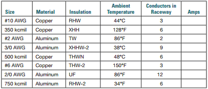
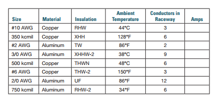
Use the NEC to determine the ampacity of the following conductors.
To find:
The ohms-per-mil-foot of an aluminum conductor located in an area with a temperature of 104°F (40°C). Also, use the NEC to determine the ampacity of the following conductors.
Answer to Problem 10PP
The resistance of a 16 AWG copper conductor is 1.27 ohms.
Explanation of Solution
The resistivity, K of the conductor at temperature T is
where, Rref is the resistance at 20°C
From Figure 10-16, the value of Rref can be obtained
Tref is the reference temperature (20°C)
Substituting the values, we get
(a) From Table 310.15(B)(16), we know that the maximum ampacity of a 10 AWG copper conductor of Type RHW insulation is 35A and the rated temperature is
Thus, from Table 310.15(B)(2)(a), the correction factor of the ambient air temperature at
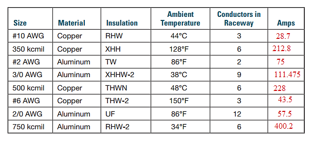
Thus, after correction, the ampacity will be
(b) From Table 310.15(B)(16), we know that the maximum ampacity of a 350 kcmil copper conductor of Type XHH insulation is 350A and the rated temperature is
Thus, from Table 310.15(B)(2)(a), the correction factor of the ambient air temperature at
Thus, after correction, the ampacity will be
If a raceway is to contain more than three conductors, the ampacity of the conductors must be de-rated. The correction factors for six copper conductors is 80%. Thus, after correction, the ampacity will be
(c) From Table 310.15(B)(16), we know that the maximum ampacity of a 2 AWG aluminum conductor of Type TW insulation is 75A and the rated temperature is
Thus, from Table 310.15(B)(2)(a), the correction factor of the ambient air temperature at
Thus, after correction, the ampacity will be
(d) From Table 310.15(B)(16), we know that the maximum ampacity of a 3/0 AWG aluminum conductor of Type XHHW-2 insulation is 175A and the rated temperature is
Thus, from Table 310.15(B)(2)(a), the correction factor of the ambient air temperature at
Thus, after correction, the ampacity will be
If a raceway is to contain more than three conductors, the ampacity of the conductors must be de-rated. The correction factors for nine aluminum conductors is 70%. Thus, after correction, the ampacity will be
(e) From Table 310.15(B)(16), we know that the maximum ampacity of a 500 kcmil copper conductor of Type THWN insulation is 380A and the rated temperature is
Thus, from Table 310.15(B)(2)(a), the correction factor of the ambient air temperature at
Thus, after correction, the ampacity will be
If a raceway is to contain more than three conductors, the ampacity of the conductors must be de-rated. The correction factors for six copper conductors is 80%. Thus, after correction, the ampacity will be
(f) From Table 310.15(B)(16), we know that the maximum ampacity of a 6 AWG copper conductor of Type THW-2 insulation is 75A and the rated temperature is
Thus, from Table 310.15(B)(2)(a), the correction factor of the ambient air temperature at
Thus, after correction, the ampacity will be
(g) From Table 310.15(B)(16), we know that the maximum ampacity of a 2/0 AWG aluminum conductor of Type UF insulation is 115A and the rated temperature is
Thus, from Table 310.15(B)(2)(a), the correction factor of the ambient air temperature at
Thus, after correction, the ampacity will be
If a raceway is to contain more than three conductors, the ampacity of the conductors must be de-rated. The correction factors for 12 aluminum conductors is 50%. Thus, after correction, the ampacity will be
(h) From Table 310.15(B)(16), we know that the maximum ampacity of a 750 kcmil aluminum conductor of Type RHW-2 insulation is 435A and the rated temperature is
Thus, from Table 310.15(B)(2)(a), the correction factor of the ambient air temperature at
Thus, after correction, the ampacity will be
If a raceway is to contain more than three conductors, the ampacity of the conductors must be de-rated. The correction factors for 6 aluminum conductors is 80%. Thus, after correction, the ampacity will be
Thus, the table will be:
Want to see more full solutions like this?
Chapter 11 Solutions
Delmar's Standard Textbook of Electricity (MindTap Course List)


- 4. Find the differential equation of the following system whose transfer function is given by S+3 H(s) = s3 +3s+2arrow_forwardPreliminary Laboratory (Prelab) Work Complete the following tasks in the space provided below for the circuit shown in Figure 2. 1. Use voltage division to compute the phasor voltages VR and Vc assuming nominal values of R = 1000[2], C = 0.01[u], and a cosinusoidal time-domain source voltage signal given by equation 5 below. Voltage division must be used to receive any credit. (10 points) equation (5) Vs(t) = VRMSCOS(ct + 0) = 5cos(@t + 0) = 5cos(62832t + 0) = 5cos(62832t) [V] =VRMSCOS(2лft + 0) = 5cos[2л(10000)t + 0] = 5cos[2л(10000)t] [V] 2. Compute the phasor current, Is. (3 points) 3. Calculate the complex power, S, active power, P, and reactive power, Q, for the circuit. (4 points) 4. Construct the phasor diagram for the circuit, and show mathematically that the phasor (vector) sum of the phasor voltages VR and Vc is equal to Vs. (3 points) Agilent 33210A (BECC4242) or Vs Keysight 33500B (BECC4261) Function Generators Is R w + VR Vc + + Zc V out =Vc Figure 2: RC circuit connected…arrow_forwardPlease explain in detail. My answer for the first question is 15/2. I am more confused about how to do the graphing part and figure how long it will take to reach its final value. Thank you, I will like this.arrow_forward
- This is the 3rd time i'm asking this. SOLVE THIS AND FIND V0 , the last answer i was given is -2V which is not even one of the listed options. the listed options are: 12V,4V,24V,6V. first answer given to me was 4V but after i simulated on ltspice albeit i'm not sure if i simulated correct i got a different answer and when i solved it myself i got a different answer. this is my last remaining question. PLEASE SOLVE CORRECTLY AND PROPERLY. NODAL ANALYSIS IS BEST TO USE HERE. IT IS AN IDEAL OP-AMP. SIMULATE USING LTSPICE AND GIVE ME FINAL ANSWER IF POSSIBLE AS THAT IS ALL I CARE ABOUT NOT THE PROCESS. THANK YOU. WILL UPVOTE CORRECT ANSWER, but downvote wrong answer.arrow_forwardFind the exact value of V0. This question was already asked here and the answer was 4V i solved it myself and got a different answer and when i simulated it i also got a different answer.But i might be wrong. so please solve this for me and IF POSSIBLE simulate it so we can be 100% sure that the answer is correct as it's very important that i understand where i went wrong.arrow_forwardFind load flow Solution 1.2 20 Z12 = 0.01+jo.03 in Z₁4=0.02+0.04 и а 9.01+10.03 0.02+0.04 0.01+0.03 58-1 Vek 1.05 100 MVA Pe=230 MW 150 MW w 140 MW 01012 +0.035 80 M√ar 723=0.01+0.03 90 mvare Z34 = 0.012+ 10.035arrow_forward
- SD = 100 MVA 1.12° 150mw ← 0.01+0.03 10.02 -0.04 Too M P = 250 MW 0.02+0.04 0.012 jo.03 $ (V3)=1.05 P.4 -03 = = 200 MW 212=0.01+10.03 Zzze 0.02 +10.04 214=0.02+10.04 Z34 = 0.012+10.03arrow_forwardChoose the correct answer to the following questions: 1- What is the total power radiated in Watts for the power density W = a) 4π² b) 8m²/3 2- Fresnel zone is also called as sine W/m²? 3r² c) 4π²/3 d) 2π²/3 a) Near Field b) Far Field c) Electrostatic Field d) Reactive Field 3- The far-field distance at 900 MHz, if the maximum antenna dimension is 0.75 m is.... a) 3.375 m b) 3.5m c) 3.375 cm d) none 4- The antenna gain is on input power to antenna and on power due to ohmic losses. c) Independent, dependent d) a) Independent, independent b) Dependent, independent Dependent, dependent 5- If beam width of the antenna increases, then directivity. a) Decreases b) Increases c) Remains unchanged d) Depends on type of antennaarrow_forwardplease solve this and clarify each step. thanksarrow_forward
- The input reactance of 1/2 dipole with radius of 1/30 is given as shown in figure below, Assuming the wire of dipole is conductor 5.6*107 S/m, determine at f=1 GHz the a- Loss resistance, b- Radiation efficiency c- Reflection efficiency when the antenna is connected to T.L shown in the figure. Rr Ro= 50 2 Avg/4 RL -j100 [In(l/a) 1.5] tan(ẞ1)arrow_forwardFind Zeq here. i already had one solution written to me but it's wrong. my main question is. i know that i do the parallel connection first so 2x2 / 2+2 = 1ohm but what i'm asking is since it's an open terminal is R3,2(parallel resistors) in series to R1? or should i first do R3,2 // to ZL and then add R1 in series? PLEASE READ THIS. and solve properly. EXPLAIN WHAT I ASKED PROPERLY. UPVOTE WILL BE GIVEN.arrow_forwardThe E-field pattern of an antenna, independent of o, varies as follows: E = 0 7100 0° ≤0≤45° 45° < 0 ≤ 90° 90° < 0 ≤ 180° (a) What is the directivity of this antenna? (b) What is the radiation resistance of the antenna at 200 m from it if the field is equal to 10 V/m (rms) for 0 = 0° at that distance and the terminal current is 5 A (rms)?arrow_forward
 Power System Analysis and Design (MindTap Course ...Electrical EngineeringISBN:9781305632134Author:J. Duncan Glover, Thomas Overbye, Mulukutla S. SarmaPublisher:Cengage Learning
 Delmar's Standard Textbook Of ElectricityElectrical EngineeringISBN:9781337900348Author:Stephen L. HermanPublisher:Cengage Learning
 Electricity for Refrigeration, Heating, and Air C...Mechanical EngineeringISBN:9781337399128Author:Russell E. SmithPublisher:Cengage Learning