
Videos
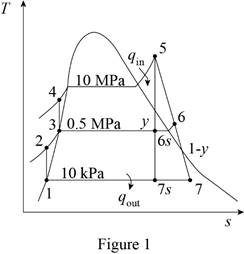
Consider a steam power plant that operates on a regenerative Rankine cycle and has a net power output of 150 MW. Steam enters the turbine at 10 MPa and 500°C and the condenser at 10 kPa. The isentropic efficiency of the turbine is 80 percent, and that of the pumps is 95 percent. Steam is extracted from the turbine at 0.5 MPa to heat the feedwater in an open feedwater heater. Water leaves the feedwater heater as a saturated liquid. Show the cycle on a T-s diagram, and determine (a) the mass flow rate of steam through the boiler and (b) the thermal efficiency of the cycle. Also, determine the exergy destruction associated with the regeneration process. Assume a source temperature of 1300 K and a sink temperature of 303 K.
(a)
The mass flow rate of steam through the boiler.
Answer to Problem 98RP
The mass flow rate of steam through the boiler is
Explanation of Solution
Draw the
Here, water (steam) is the working fluid of the regenerative Rankine cycle. The cycle involves two pumps.
Write the formula for work done by the pump during process 1-2.
Here, the specific volume is
Write the formula for enthalpy
Write the formula for work done by the pump during process 3-4.
Here, the specific volume is
Write the formula for enthalpy
At state
The steam expanded to the pressure of
The quality of water at state
The enthalpy at state
Here, the enthalpy is
The isentropic efficiency for the process 5-6 is expressed as follows.
At state
The steam enters the condenser at the pressure of
The quality of water at state
The enthalpy at state
Here, the subscript
The isentropic efficiency for the process 5-7 is expressed as follows.
Here, the subscript
Write the formula for heat in
Here, the mass fraction steam extracted from the turbine to the inlet mass of the boiler
Write the general equation of energy balance equation.
Here, the rate of net energy inlet is
At steady state the rate of change of net energy of the system
Refer Equation (XIII).
Write the energy balance equation for open feed water heater.
Rewrite the Equation (XIV) in terms of mass fraction
Write the formula for net work output of the cycle.
Write the formula for mass flow rate of steam.
Here, the net power output of the cycle is
At state 1: (Pump I inlet)
The water exits the condenser as a saturated liquid at the pressure of
Refer Table A-5, “Saturated water-Pressure table”.
The enthalpy
At state 3: (Pump II inlet)
The water exits the open feed water heater as a saturated liquid at the pressure of
Refer Table A-5, “Saturated water-Pressure table”.
The enthalpy
At state 5:
The steam enters the turbine as superheated vapor.
Refer Table A-6, “Superheated water”.
The enthalpy
Refer Figure 1.
At state
The steam expanded to the pressure of
Refer Table A-5, “Saturated water-Pressure table”.
Obtain the following properties corresponding to the pressure of
At state
The steam enters the condenser at the pressure of
Refer Table A-5, “Saturated water-Pressure table”.
Obtain the following properties corresponding to the pressure of
Conclusion:
Substitute
Substitute
Substitute
Substitute
From Figure 1.
Substitute
Substitute
Equation (VI).
Substitute
Substitute
Substitute
Equation (IX).
Substitute
Substitute
Substitute
Substitute
Substitute
Substitute
Thus, the mass flow rate of steam through the boiler is
(b)
The thermal efficiency of the cycle and the exergy destruction associated with the regeneration process.
Answer to Problem 98RP
The thermal efficiency of the cycle is
Explanation of Solution
Write the formula for thermal efficiency of the cycle
Write the formula for exergy destruction associated with the regeneration cycle.
Here, the entropy generation is
Conclusion:
Substitute
Thus, the thermal efficiency of the cycle is
Consider the regeneration process- open feed water heater, process states 6,2,3.
Here,
Substitute
Thus, the exergy destruction associated with the regeneration process is
Want to see more full solutions like this?
Chapter 10 Solutions
CONNECT FOR THERMODYNAMICS: AN ENGINEERI
Additional Engineering Textbook Solutions
Vector Mechanics for Engineers: Statics and Dynamics
Database Concepts (8th Edition)
Modern Database Management
Starting Out with C++ from Control Structures to Objects (9th Edition)
Thinking Like an Engineer: An Active Learning Approach (4th Edition)
Automotive Technology: Principles, Diagnosis, And Service (6th Edition) (halderman Automotive Series)


- Question 1. Draw 3 teeth for the following pinion and gear respectively. The teeth should be drawn near the pressure line so that the teeth from the pinion should mesh those of the gear. Drawing scale (1:1). Either a precise hand drawing or CAD drawing is acceptable. Draw all the trajectories of the involute lines and the circles. Specification: 18tooth pinion and 30tooth gear. Diameter pitch=P=6 teeth /inch. Pressure angle:20°, 1/P for addendum (a) and 1.25/P for dedendum (b). For fillet, c=b-a.arrow_forward5. The figure shows a gear train. There is no friction at the bearings except for the gear tooth forces. The material of the milled gears is steel having a Brinell hardness of 170. The input shaft speed (n2) is 800 rpm. The face width and the contact angle for all gears are 1 in and 20° respectively. In this gear set, the endurance limit (Se) is 15 kpsi and nd (design factor) is 2. (a) Find the revolution speed of gear 5. (b) Determine whether each gear satisfies the design factor of 2.0 for bending fatigue. (c) Determine whether each gear satisfies the design factor of 2.0 for surface fatigue (contact stress). (d) According to the computation results of the questions (b) and (c), explain the possible failure mechanisms for each gear. N4=28 800rpm N₁=43 N5=34 N₂=14 P(diameteral pitch)=8 for all gears Coupled to 2.5hp motorarrow_forward1. The rotating steel shaft is simply supported by bearings at points of B and C, and is driven by a spur gear at D, which has a 6-in pitch diameter. The force F from the drive gear acts at a pressure angle of 20°. The shaft transmits a torque to point A of TA =3000 lbĘ in. The shaft is machined from steel with Sy=60kpsi and Sut=80 kpsi. (1) Draw a shear force diagram and a bending moment diagram by F. According to your analysis, where is the point of interest to evaluate the safety factor among A, B, C, and D? Describe the reason. (Hint: To find F, the torque Tд is generated by the tangential force of F (i.e. Ftangential-Fcos20°) When n=2.5, K=1.8, and K₁ =1.3, determine the diameter of the shaft based on (2) static analysis using DE theory (note that fatigue stress concentration factors need to be used for this question because the loading condition is fatigue) and (3) a fatigue analysis using modified Goodman. Note) A standard diameter is not required for the questions. 10 in Darrow_forward
- 3 N2=28 P(diametral pitch)=8 for all gears Coupled to 25 hp motor N3=34 Full depth spur gears with pressure angle=20° N₂=2000 rpm (1) Compute the circular pitch, the center-to-center distance, and base circle radii. (2) Draw the free body diagram of gear 3 and show all the forces and the torque. (3) In mounting gears, the center-to-center distance was reduced by 0.1 inch. Calculate the new values of center-to-center distance, pressure angle, base circle radii, and pitch circle diameters. (4)What is the new tangential and radial forces for gear 3? (5) Under the new center to center distance, is the contact ratio (mc) increasing or decreasing?arrow_forward2. A flat belt drive consists of two 4-ft diameter cast-iron pulleys spaced 16 ft apart. A power of 60 hp is transmitted by a pulley whose speed is 380 rev/min. Use a service factor (Ks) pf 1.1 and a design factor 1.0. The width of the polyamide A-3 belt is 6 in. Use CD=1. Answer the following questions. (1) What is the total length of the belt according to the given geometry? (2) Find the centrifugal force (Fc) applied to the belt. (3) What is the transmitted torque through the pulley system given 60hp? (4) Using the allowable tension, find the force (F₁) on the tight side. What is the tension at the loose side (F2) and the initial tension (F.)? (5) Using the forces, estimate the developed friction coefficient (f) (6) Based on the forces and the given rotational speed, rate the pulley set. In other words, what is the horse power that can be transmitted by the pulley system? (7) To reduce the applied tension on the tight side, the friction coefficient is increased to 0.75. Find out the…arrow_forwardThe tooth numbers for the gear train illustrated are N₂ = 24, N3 = 18, №4 = 30, №6 = 36, and N₁ = 54. Gear 7 is fixed. If shaft b is turned through 5 revolutions, how many turns will shaft a make? a 5 [6] barrow_forward
- Please do not use any AI tools to solve this question. I need a fully manual, step-by-step solution with clear explanations, as if it were done by a human tutor. No AI-generated responses, please.arrow_forwardPlease do not use any AI tools to solve this question. I need a fully manual, step-by-step solution with clear explanations, as if it were done by a human tutor. No AI-generated responses, please.arrow_forwardCE-112 please solve this problem step by step and give me the correct answerarrow_forward
 Elements Of ElectromagneticsMechanical EngineeringISBN:9780190698614Author:Sadiku, Matthew N. O.Publisher:Oxford University Press
 Mechanics of Materials (10th Edition)Mechanical EngineeringISBN:9780134319650Author:Russell C. HibbelerPublisher:PEARSON
 Thermodynamics: An Engineering ApproachMechanical EngineeringISBN:9781259822674Author:Yunus A. Cengel Dr., Michael A. BolesPublisher:McGraw-Hill Education
 Control Systems EngineeringMechanical EngineeringISBN:9781118170519Author:Norman S. NisePublisher:WILEY
 Mechanics of Materials (MindTap Course List)Mechanical EngineeringISBN:9781337093347Author:Barry J. Goodno, James M. GerePublisher:Cengage Learning
 Engineering Mechanics: StaticsMechanical EngineeringISBN:9781118807330Author:James L. Meriam, L. G. Kraige, J. N. BoltonPublisher:WILEY