
Videos
The schematic of a single-flash geothermal power plant with state numbers is given in Fig. P10–69. Geothermal resource exists as saturated liquid at 230°C. The geothermal liquid is withdrawn from the production well at a rate of 230 kg/s and is flashed to a pressure of 500 kPa by an essentially isenthalpic flashing process where the resulting vapor is separated from the liquid in a separator and is directed to the turbine. The steam leaves the turbine at 10 kPa with a moisture content of 5 percent and enters the condenser where it is condensed; it is routed to a reinjection well along with the liquid coming off the separator. Determine (a) the power output of the turbine and the thermal efficiency of the plant, (b) the exergy of the geothermal liquid at the exit of the flash chamber, and the exergy destructions and the second-law efficiencies for (c) the turbine and (d) the entire plant.
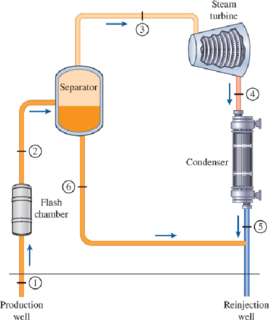
FIGURE P10–69
(a)
The temperature of the steam after the flashing process and the power output from the turbine if the pressure of the steam at the exit of flash chamber is
Answer to Problem 69P
The power output turbine is
The thermal efficiency of the plant is
Explanation of Solution
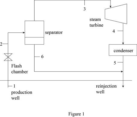
Draw schematic diagram of single flash geothermal power plant as shown in Figure 1.
Write the general energy rate balance equation.
Here, the rate of total energy in is
Consider the system operates at steady state. Hence, the rate of change in net energy of the system becomes zero.
The Equation (I) is reduced as follows.
Refer Figure 1.
The flash chamber is nothing but the expansion valve. At expansion valve, the enthalpy kept constant.
Express the energy balance equation for the flash chamber.
Express the energy balance equation for the separator.
Express the energy balance equation for the turbine.
At state 1:
The geothermal water is extracted at the state of saturated liquid at the temperature of
The enthalpy and entropy at state 1 is as follows.
Refer Table A-4, “Saturated water-Temperature table”
The enthalpy
Refer Table A-1, “Molar mass, gas constant, and critical-point properties”.
At state 2:
The exit pressure of the flash chamber is
The geothermal steam is flashed at constant enthalpy. The exit steam of the flash chamber is at the quality of
Here, the fluid enthalpy is
Refer Table A-5, “Saturated water-Pressure table”.
Obtain the following corresponding to the pressure of
The entropy
Write the formula for mass flow rate of vapor at entering the turbine.
Here, the mass flow rate is
At state 3:
There is no pressure drop in the separator. The separator separates vapor and liquid form the flashed steam, and the separated vapor alone sent to the turbine.
The enthalpy
Refer Table A-5, “Saturated water-Pressure table”.
The enthalpy
At state 4:
The steam is at the state of saturated mixture at the pressure of
The quality at state 4 is as follows.
The enthalpy
Refer Table A-5, “Saturated water-Pressure table”.
Obtain the following corresponding to the pressure of
At state 6:
The saturated water only exits at the bottom of the separator. The enthalpy
Refer Table A-5, “Saturated water-Pressure table”.
The enthalpy
Write the formula for net energy input of the plant.
Write the formula for thermal efficiency.
Consider, the surrounding temperature is
The surrounding enthalpy
Refer Table A-4, “Saturated water-Temperature table”.
The enthalpy
Conclusion:
Substitute
Substitute
Substitute
Substitute
Equation (VII).
Substitute
Substitute
Equation (III).
Thus, the power output turbine is
Substitute
Equation (IX).
Substitute
Thus, the thermal efficiency of the plant is
(b)
The exergy of the geothermal liquid at the exit of the flash chamber, and the exergy destructions.
Answer to Problem 69P
The exergy of the geothermal liquid at the exit of the flash chamber, and the exergy destruction is
Explanation of Solution
Write the formula for exergy of the steam at their respective process state.
Here, the enthalpy is
Write the formula for rate of exergy destruction at the exit of flash chamber (state 6).
Here, the rate of exergy destruction at state 6 is
Conclusion:
For process state 1:
Substitute
For process state 2:
Substitute
For process state 3:
Substitute
For process state 4:
Substitute
For process state 6:
Substitute
The mass flow rate of water at the bottom exit of separator (state 6) is expressed as follows.
Substitute
Thus, the exergy of the geothermal liquid at the exit of the flash chamber, and the exergy destruction is
(c)
The exergy destruction and second law of efficiency for the turbine.
Answer to Problem 69P
The exergy destruction and second law of efficiency for the turbine is
Explanation of Solution
Write the formula for rate of exergy destruction of the turbine.
Write the formula for second law of efficiency of the turbine.
Conclusion:
Substitute
Substitute
Thus, the exergy destruction and second law of efficiency for the turbine is
(d)
The exergy destruction and second law of efficiency for the entire plant.
Answer to Problem 69P
The exergy destruction and second law of efficiency for the plant is
Explanation of Solution
Write the formula for rate of exergy input of the plant.
Write the formula for rate of exergy destruction of the plant.
Write the formula for second law of efficiency of the plant.
Conclusion:
Substitute
Substitute
Substitute
Thus, the exergy destruction and second law of efficiency for the plant is
Want to see more full solutions like this?
Chapter 10 Solutions
CONNECT FOR THERMODYNAMICS: AN ENGINEERI


- 1. The rotating steel shaft is simply supported by bearings at points of B and C, and is driven by a spur gear at D, which has a 6-in pitch diameter. The force F from the drive gear acts at a pressure angle of 20°. The shaft transmits a torque to point A of TA =3000 lbĘ in. The shaft is machined from steel with Sy=60kpsi and Sut=80 kpsi. (1) Draw a shear force diagram and a bending moment diagram by F. According to your analysis, where is the point of interest to evaluate the safety factor among A, B, C, and D? Describe the reason. (Hint: To find F, the torque Tд is generated by the tangential force of F (i.e. Ftangential-Fcos20°) When n=2.5, K=1.8, and K₁ =1.3, determine the diameter of the shaft based on (2) static analysis using DE theory (note that fatigue stress concentration factors need to be used for this question because the loading condition is fatigue) and (3) a fatigue analysis using modified Goodman. Note) A standard diameter is not required for the questions. 10 in Darrow_forward3 N2=28 P(diametral pitch)=8 for all gears Coupled to 25 hp motor N3=34 Full depth spur gears with pressure angle=20° N₂=2000 rpm (1) Compute the circular pitch, the center-to-center distance, and base circle radii. (2) Draw the free body diagram of gear 3 and show all the forces and the torque. (3) In mounting gears, the center-to-center distance was reduced by 0.1 inch. Calculate the new values of center-to-center distance, pressure angle, base circle radii, and pitch circle diameters. (4)What is the new tangential and radial forces for gear 3? (5) Under the new center to center distance, is the contact ratio (mc) increasing or decreasing?arrow_forward2. A flat belt drive consists of two 4-ft diameter cast-iron pulleys spaced 16 ft apart. A power of 60 hp is transmitted by a pulley whose speed is 380 rev/min. Use a service factor (Ks) pf 1.1 and a design factor 1.0. The width of the polyamide A-3 belt is 6 in. Use CD=1. Answer the following questions. (1) What is the total length of the belt according to the given geometry? (2) Find the centrifugal force (Fc) applied to the belt. (3) What is the transmitted torque through the pulley system given 60hp? (4) Using the allowable tension, find the force (F₁) on the tight side. What is the tension at the loose side (F2) and the initial tension (F.)? (5) Using the forces, estimate the developed friction coefficient (f) (6) Based on the forces and the given rotational speed, rate the pulley set. In other words, what is the horse power that can be transmitted by the pulley system? (7) To reduce the applied tension on the tight side, the friction coefficient is increased to 0.75. Find out the…arrow_forward
- The tooth numbers for the gear train illustrated are N₂ = 24, N3 = 18, №4 = 30, №6 = 36, and N₁ = 54. Gear 7 is fixed. If shaft b is turned through 5 revolutions, how many turns will shaft a make? a 5 [6] barrow_forwardCE-112 please solve this problem step by step and give me the correct answerarrow_forwardCE-112 please solve this problem step by step and give me the correct answerarrow_forward
- CE-112 solve this problem step by step and give me the correct answer pleasearrow_forwardPlease do not use any AI tools to solve this question. I need a fully manual, step-by-step solution with clear explanations, as if it were done by a human tutor. No AI-generated responses, please.arrow_forwardPlease do not use any AI tools to solve this question. I need a fully manual, step-by-step solution with clear explanations, as if it were done by a human tutor. No AI-generated responses, please.arrow_forward
 Principles of Heat Transfer (Activate Learning wi...Mechanical EngineeringISBN:9781305387102Author:Kreith, Frank; Manglik, Raj M.Publisher:Cengage Learning
 Refrigeration and Air Conditioning Technology (Mi...Mechanical EngineeringISBN:9781305578296Author:John Tomczyk, Eugene Silberstein, Bill Whitman, Bill JohnsonPublisher:Cengage Learning
 Welding: Principles and Applications (MindTap Cou...Mechanical EngineeringISBN:9781305494695Author:Larry JeffusPublisher:Cengage Learning