
Videos
Reconsider Prob. 10–83. Determine which components of the combined cycle are the most wasteful of work potential.
10–83 A combined gas–steam power cycle uses a simple gas turbine for the topping cycle and simple Rankine cycle for the bottoming cycle. Atmospheric air enters the gas turbine at 101 kPa and 20°C, and the maximum gas cycle temperature is 1100°C. The compressor pressure ratio is 8; the compressor isentropic efficiency is 85 percent; and the gas turbine isentropic efficiency is 90 percent. The gas stream leaves the heat exchanger at the saturation temperature of the steam flowing through the heat exchanger. Steam flows through the heat exchanger with a pressure of 6000 kPa and leaves at 320°C. The steam-cycle condenser operates at 20 kPa, and the isentropic efficiency of the steam turbine is 90 percent. Determine the mass flow rate of air through the air compressor required for this system to produce 100 MW of power. Use constant specific heats for air at room temperature.
Which component of the combined cycle is the most wasteful of work potential.
Answer to Problem 85P
The combustor of the gas-steam cycle has largest exergy destruction
Explanation of Solution
Show the
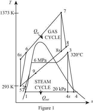
Refer Figure 1.
Consider the gas cycle (topping cycle) and their respective process states such as 5, 6,
Write the temperature and pressure relation at isentropic state and for the process 5-6-
Here, the temperature is
Write the formula for isentropic efficiency of compressor for the process 5-6-
Here, the enthalpy is
Rearrange and rewrite the equation (II) to obtain
Write the temperature and pressure relation at isentropic state and for the process 7-8-
Write the formula for isentropic efficiency of gas turbine
Rearrange and rewrite the equation (V) to obtain
At state 9: (heat exchanger)
The temperature
Refer Table A-5, “Saturated water-Pressure table”.
The saturation temperature corresponding to the pressure of
Refer Figure 1.
Consider the steam cycle (bottoming cycle) and their respective process states such as 1, 2, 3, 4,
At state 1:
The water exits the condenser as a saturated liquid at the pressure of
Refer Table A-5, “Saturated water-Pressure table”.
The enthalpy
At state 2:
Write the formula for work done by the pump during process 1-2.
Here, the specific volume is
Write the formula for enthalpy
At state 3: (Turbine inlet)
The steam enters the turbine as superheated vapour.
Refer Table A-6, “Superheated water”.
The enthalpy
From Figure 1,
At state 4: (Turbine exit or condenser inlet)
The steam exits the condenser as a saturated liquid at the pressure of
The quality of water at the exit of the turbine is expressed as follows.
The enthalpy at state
Here, the enthalpy is
Refer Table A-5, “Saturated water-Pressure table”.
Obtain the following properties corresponding to the pressure of
Write the formula for isentropic efficiency of the steam turbine
Rearrange the Equation (XI) to obtain the enthalpy
Write the formula for net work output of the gas cycle.
Here, the specific heat of air at constant pressure is
Write the formula for net work output of the steam cycle.
Write the general energy rate balance equation.
Here, the rate of energy in is
Consider the heat exchanger operates on steady state. Hence, the rate of change in net energy of the system is zero.
The Equation (XV) is reduced as follows for the heat exchanger.
Here, the mass flow rate of air is
Write the formula for mass flow rate of air through the compressor.
Write the formula for the exergy destruction for the process 3-4 (turbine).
Write the formula for the exergy destruction for the process 4-1 (condenser).
Write the formula for the exergy destruction for heat exchanger.
Write the formula for the exergy destruction for the process 5-6 (compressor).
Write the formula for the exergy destruction for the process 6-7 (combustion chamber).
Write the formula for the exergy destruction for the process 7-8 (gas turbine).
Here, the specific heat at constant pressure of air is
Refer Table A-2, “Ideal-gas specific heats of various common gases”.
The specific heat at constant pressure
Conclusion:
Substitute
Substitute
Substitute
Substitute
Substitute
Substitute
Here,
Substitute
Substitute
Equation (X).
Substitute
Substitute
Substitute
Equation (XIV).
Substitute
When, the mass flow rate of air is
Substitute
Thus, the Equation (XXIV) describes that
Substitute
Thus, the mass flow rate of the air through the air compressor required for this system to produce
Substitute
Consider the process 1 to 2 (Pump).
Here, the pump is isentropic. Hence the exergy destruction during the process 1-2 is zero.
Consider the process 3 to 4 (steam turbine).
Here,
Substitute
Thus, the exergy destruction during process 3-4 is
Substitute
Substitute
Substitute
Substitute
Substitute
The calculated exergy destruction value is greater for component combustor that is
Hence, the combustor of the gas-steam cycle has largest exergy destruction of all other components and that is the most wasteful of work potential.
Want to see more full solutions like this?
Chapter 10 Solutions
THERMODYNAMICS-SI ED. EBOOK >I<
Additional Engineering Textbook Solutions
Automotive Technology: Principles, Diagnosis, And Service (6th Edition) (halderman Automotive Series)
Starting Out With Visual Basic (8th Edition)
Starting Out with Programming Logic and Design (5th Edition) (What's New in Computer Science)
Java How to Program, Early Objects (11th Edition) (Deitel: How to Program)
Mechanics of Materials (10th Edition)
Java: An Introduction to Problem Solving and Programming (8th Edition)


- Experiment تكنولوجيا السيارات - Internal Forced convenction Heat transfer Air Flow through Rectangular Duct. objective: Study the convection heat transfer of air flow through rectangular duct. Valve Th Top Dead Centre Exhaust Valve Class CP. N; ~ RIVavg Ti K 2.11 Te To 18.8 21.3 45.8 Nath Ne Pre Calculations:. Q = m cp (Te-Ti) m: Varg Ac Acca*b Q=hexp As (Ts-Tm) 2 2.61 18.5 20.846.3 Tm = Te-Ti = 25 AS-PL = (a+b)*2*L Nu exp= Re-Vavy D heep Dh k 2ab a+b Nu Dh the- (TS-Tm) Ts. Tmy Name / Nu exp Naxe بب ارتدان العشريarrow_forwardProcedure:1- Cartesian system, 2D3D,type of support2- Free body diagram3 - Find the support reactions4- If you find a negativenumber then flip the force5- Find the internal force3D∑Fx=0∑Fy=0∑Fz=0∑Mx=0∑My=0\Sigma Mz=02D\Sigma Fx=0\Sigma Fy=0\Sigma Mz=05- Use method of sectionand cut the elementwhere you want to findarrow_forwardProcedure:1- Cartesian system, 2D3D,type of support2- Free body diagram3 - Find the support reactions4- If you find a negativenumber then flip the force5- Find the internal force3D∑Fx=0∑Fy=0∑Fz=0∑Mx=0∑My=0\Sigma Mz=02D\Sigma Fx=0\Sigma Fy=0\Sigma Mz=05- Use method of sectionand cut the elementwhere you want to findthe internal force andkeep either side of thearrow_forward
- Procedure: 1- Cartesian system, 2D3D, type of support 2- Free body diagram 3 - Find the support reactions 4- If you find a negative number then flip the force 5- Find the internal force 3D ∑Fx=0 ∑Fy=0 ∑Fz=0 ∑Mx=0 ∑My=0 ΣMz=0 2D ΣFx=0 ΣFy=0 ΣMz=0 5- Use method of section and cut the element where you want to find the internal force and keep either side of thearrow_forwardProcedure:1- Cartesian system, 2D3D,type of support2- Free body diagram3 - Find the support reactions4- If you find a negativenumber then flip the force5- Find the internal force3D∑Fx=0∑Fy=0∑Fz=0∑Mx=0∑My=0\Sigma Mz=02D\Sigma Fx=0\Sigma Fy=0\Sigma Mz=05- Use method of sectionand cut the elementwhere you want to findthe internal force andkeep either side of thearrow_forwardProcedure: 1- Cartesian system, 2(D)/(3)D, type of support 2- Free body diagram 3 - Find the support reactions 4- If you find a negative number then flip the force 5- Find the internal force 3D \sum Fx=0 \sum Fy=0 \sum Fz=0 \sum Mx=0 \sum My=0 \Sigma Mz=0 2D \Sigma Fx=0 \Sigma Fy=0 \Sigma Mz=0 5- Use method of section and cut the element where you want to find the internal force and keep either side of the sectionarrow_forward
- Procedure: 1- Cartesian system, 2(D)/(3)D, type of support 2- Free body diagram 3 - Find the support reactions 4- If you find a negative number then flip the force 5- Find the internal force 3D \sum Fx=0 \sum Fy=0 \sum Fz=0 \sum Mx=0 \sum My=0 \Sigma Mz=0 2D \Sigma Fx=0 \Sigma Fy=0 \Sigma Mz=0 5- Use method of section and cut the element where you want to find the internal force and keep either side of the sectionarrow_forwardFor each system below with transfer function G(s), plot the pole(s) on the s-plane. and indicate whether the system is: (a) "stable" (i.e., a bounded input will always result in a bounded output), (b) "marginally stable," or (c) "unstable" Sketch a rough graph of the time response to a step input. 8 a) G(s) = 5-5 8 b) G(s) = c) G(s) = = s+5 3s + 8 s² - 2s +2 3s +8 d) G(s): = s²+2s+2 3s+8 e) G(s): = s² +9 f) G(s): 8 00 == Sarrow_forwardPlease answer the following question. Include all work and plase explain. Graphs are provided below. "Consider the Mg (Magnesium) - Ni (Nickel) phase diagram shown below. This phase diagram contains two eutectic reactions and two intermediate phases (Mg2Ni and MgNi2). At a temperature of 505oC, determine what the composition of an alloy would need to be to contain a mass fraction of 0.20 Mg and 0.80 Mg2Ni."arrow_forward
- The triangular plate, having a 90∘∘ angle at AA, supports the load PP = 370 lblb as shown in (Figure 1).arrow_forwardDesign a 4-bar linkage to carry the body in Figure 1 through the two positions P1 and P2 at the angles shown in the figure. Use analytical synthesis with the free choice values z = 1.075, q= 210°, ß2 = −27° for left side and s = 1.24, y= 74°, ½ = − 40° for right side. φ 1.236 P2 147.5° 210° 2.138 P1 Figure 1 Xarrow_forwardDesign a 4-bar linkage to carry the body in Figure 1 through the two positions P1 and P2 at the angles shown in the figure. Use analytical synthesis with the free choice values z = 1.075, q= 210°, B₂ = −27° for left side and s = 1.24, y= 74°, ½ = − 40° for right side. 1.236 P2 147.5° 210° P1 Figure 1 2.138 Xarrow_forward
 Elements Of ElectromagneticsMechanical EngineeringISBN:9780190698614Author:Sadiku, Matthew N. O.Publisher:Oxford University Press
 Mechanics of Materials (10th Edition)Mechanical EngineeringISBN:9780134319650Author:Russell C. HibbelerPublisher:PEARSON
 Thermodynamics: An Engineering ApproachMechanical EngineeringISBN:9781259822674Author:Yunus A. Cengel Dr., Michael A. BolesPublisher:McGraw-Hill Education
 Control Systems EngineeringMechanical EngineeringISBN:9781118170519Author:Norman S. NisePublisher:WILEY
 Mechanics of Materials (MindTap Course List)Mechanical EngineeringISBN:9781337093347Author:Barry J. Goodno, James M. GerePublisher:Cengage Learning
 Engineering Mechanics: StaticsMechanical EngineeringISBN:9781118807330Author:James L. Meriam, L. G. Kraige, J. N. BoltonPublisher:WILEY