
Videos
Reconsider Prob. 10–83. Determine which components of the combined cycle are the most wasteful of work potential.
10–83 A combined gas–steam power cycle uses a simple gas turbine for the topping cycle and simple Rankine cycle for the bottoming cycle. Atmospheric air enters the gas turbine at 101 kPa and 20°C, and the maximum gas cycle temperature is 1100°C. The compressor pressure ratio is 8; the compressor isentropic efficiency is 85 percent; and the gas turbine isentropic efficiency is 90 percent. The gas stream leaves the heat exchanger at the saturation temperature of the steam flowing through the heat exchanger. Steam flows through the heat exchanger with a pressure of 6000 kPa and leaves at 320°C. The steam-cycle condenser operates at 20 kPa, and the isentropic efficiency of the steam turbine is 90 percent. Determine the mass flow rate of air through the air compressor required for this system to produce 100 MW of power. Use constant specific heats for air at room temperature.
Which component of the combined cycle is the most wasteful of work potential.
Answer to Problem 85P
The combustor of the gas-steam cycle has largest exergy destruction
Explanation of Solution
Show the
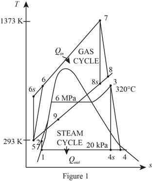
Refer Figure 1.
Consider the gas cycle (topping cycle) and their respective process states such as 5, 6,
Write the temperature and pressure relation at isentropic state and for the process 5-6-
Here, the temperature is
Write the formula for isentropic efficiency of compressor for the process 5-6-
Here, the enthalpy is
Rearrange and rewrite the equation (II) to obtain
Write the temperature and pressure relation at isentropic state and for the process 7-8-
Write the formula for isentropic efficiency of gas turbine
Rearrange and rewrite the equation (V) to obtain
At state 9: (heat exchanger)
The temperature
Refer Table A-5, “Saturated water-Pressure table”.
The saturation temperature corresponding to the pressure of
Refer Figure 1.
Consider the steam cycle (bottoming cycle) and their respective process states such as 1, 2, 3, 4,
At state 1:
The water exits the condenser as a saturated liquid at the pressure of
Refer Table A-5, “Saturated water-Pressure table”.
The enthalpy
At state 2:
Write the formula for work done by the pump during process 1-2.
Here, the specific volume is
Write the formula for enthalpy
At state 3: (Turbine inlet)
The steam enters the turbine as superheated vapour.
Refer Table A-6, “Superheated water”.
The enthalpy
From Figure 1,
At state 4: (Turbine exit or condenser inlet)
The steam exits the condenser as a saturated liquid at the pressure of
The quality of water at the exit of the turbine is expressed as follows.
The enthalpy at state
Here, the enthalpy is
Refer Table A-5, “Saturated water-Pressure table”.
Obtain the following properties corresponding to the pressure of
Write the formula for isentropic efficiency of the steam turbine
Rearrange the Equation (XI) to obtain the enthalpy
Write the formula for net work output of the gas cycle.
Here, the specific heat of air at constant pressure is
Write the formula for net work output of the steam cycle.
Write the general energy rate balance equation.
Here, the rate of energy in is
Consider the heat exchanger operates on steady state. Hence, the rate of change in net energy of the system is zero.
The Equation (XV) is reduced as follows for the heat exchanger.
Here, the mass flow rate of air is
Write the formula for mass flow rate of air through the compressor.
Write the formula for the exergy destruction for the process 3-4 (turbine).
Write the formula for the exergy destruction for the process 4-1 (condenser).
Write the formula for the exergy destruction for heat exchanger.
Write the formula for the exergy destruction for the process 5-6 (compressor).
Write the formula for the exergy destruction for the process 6-7 (combustion chamber).
Write the formula for the exergy destruction for the process 7-8 (gas turbine).
Here, the specific heat at constant pressure of air is
Refer Table A-2, “Ideal-gas specific heats of various common gases”.
The specific heat at constant pressure
Conclusion:
Substitute
Substitute
Substitute
Substitute
Substitute
Substitute
Here,
Substitute
Substitute
Equation (X).
Substitute
Substitute
Substitute
Equation (XIV).
Substitute
When, the mass flow rate of air is
Substitute
Thus, the Equation (XXIV) describes that
Substitute
Thus, the mass flow rate of the air through the air compressor required for this system to produce
Substitute
Consider the process 1 to 2 (Pump).
Here, the pump is isentropic. Hence the exergy destruction during the process 1-2 is zero.
Consider the process 3 to 4 (steam turbine).
Here,
Substitute
Thus, the exergy destruction during process 3-4 is
Substitute
Substitute
Substitute
Substitute
Substitute
The calculated exergy destruction value is greater for component combustor that is
Hence, the combustor of the gas-steam cycle has largest exergy destruction of all other components and that is the most wasteful of work potential.
Want to see more full solutions like this?
Chapter 10 Solutions
THERMODYNAMICS LLF W/ CONNECT ACCESS
Additional Engineering Textbook Solutions
Automotive Technology: Principles, Diagnosis, And Service (6th Edition) (halderman Automotive Series)
Starting Out With Visual Basic (8th Edition)
Starting Out with Programming Logic and Design (5th Edition) (What's New in Computer Science)
Java How to Program, Early Objects (11th Edition) (Deitel: How to Program)
Mechanics of Materials (10th Edition)
Java: An Introduction to Problem Solving and Programming (8th Edition)


- can you please help me perform Visual Inspection and Fractography of the attatched image: Preliminary examination to identify the fracture origin, suspected fatigue striation, and corrosion evidences.arrow_forwardcan you please help[ me conduct Causal Analysis (FTA) on the scenario attatched: FTA diagram which is a fault tree analysis diagram will be used to gain an overview of the entire path of failure from root cause to the top event (i.e., the swing’s detachment) and to identify interactions between misuse, material decay and inspection errors.arrow_forwardhi can you please help me in finding the stress intensity factor using a k-calcluator for the scenario attathced in the images.arrow_forward
- Hi, can you please help me .Identify and justify suitable analytical techniques of the scenario below, bearing in mind the kinds of information being handled to reach a conclusion (methodology). A child swing set was discovered to have failed at the fixing at the top of the chains connecting the seat to the top of the swing set. A 12 mm threaded steel bolt, connecting the shackle to the top beam, failed at the start of the threaded region on the linkage closest to the outside side of the swing set . The linkage and bolts were made of electro galvanised mild steel . The rigid bar chain alternatives and fixings were of the same material and appeared to be fitted in accordance with guidelines. The yield strength of the steel used is 260 MPa and the UTS is 380 MPa. The bolt that failed was threaded using a standard thread with a pitch (distance between threads) of 1.75 mm and a depth of approximately 1.1 mm. The swing set in question had been assigned to ‘toddlers’ with the application of…arrow_forwardHi, can you please define and calculate the failure mode of the linkage that failed on the swing (images added) : A child swing set was discovered to have failed at the fixing at the top of the chains connecting the seat to the top of the swing set. A 12 mm threaded steel bolt, connecting the shackle to the top beam, failed at the start of the threaded region on the linkage closest to the outside side of the swing set . The linkage and bolts were made of electro galvanised mild steel . The rigid bar chain alternatives and fixings were of the same material and appeared to be fitted in accordance with guidelines. The yield strength of the steel used is 260 MPa and the UTS is 380 MPa. The bolt that failed was threaded using a standard thread with a pitch (distance between threads) of 1.75 mm and a depth of approximately 1.1 mm. The swing set in question had been assigned to ‘toddlers’ with the application of a caged-type seat. However, the location was within the play area not…arrow_forwardPage 11-68. The rectangular plate shown is subjected to a uniaxial stress of 2000 psi. Compute the shear stress and the tensile developed on a plane forming an angle of 30° with the longitud axis of the member. (Hint: Assume a cross-sectional area of unity) 2000 psi 2000 psi hparrow_forward
- 11-70. A shear stress (pure shear) of 5000 psi exists on an element. (a) Determine the maximum tensile and compressive stresses caused in the element due to this shear. (b) Sketch the element showing the planes on which the maximum tensile and compressive stresses act.arrow_forward11-20. An aluminum specimen of circular cross section, 0.50 in. in diameter, ruptured under a tensile load of 12,000 lb. The plane of failure was found to be at 48° with a plane perpendicular to the longitudinal axis of the specimen. (a) Compute the shear stress on the failure plane. (b) Compute the maximum tensile stress. (c) Compute the tensile stress on the failure plane. hparrow_forwardA long flat steel bar 13 mm thick and 120 mm wide has semicircular grooves as shown and carries a tensile load of 50 kN Determine the maximum stress if plate r= 8mm r=21mm r=38mmarrow_forward
- Problem 13: F₁ = A =250 N 30% Determine the moment of each of the three forces about point B. F₂ = 300 N 60° 2 m -3 m B 4 m F3=500 Narrow_forward3 kN 3 kN 1.8 kN/m 80 mm B 300 mm D an 1.5 m-1.5 m--1.5 m- PROBLEM 5.47 Using the method of Sec. 5.2, solve Prob. 5.16 PROBLEM 5.16 For the beam and loading shown, determine the maximum normal stress due to bending on a transverse section at C.arrow_forward300 mm 3 kN 3 kN 450 N-m D E 200 mm 300 mm PROBLEM 5.12 Draw the shear and bending-moment diagrams for the beam and loading shown, and determine the maximum absolute value (a) of the shear, (b) of the bending moment.arrow_forward
 Elements Of ElectromagneticsMechanical EngineeringISBN:9780190698614Author:Sadiku, Matthew N. O.Publisher:Oxford University Press
 Mechanics of Materials (10th Edition)Mechanical EngineeringISBN:9780134319650Author:Russell C. HibbelerPublisher:PEARSON
 Thermodynamics: An Engineering ApproachMechanical EngineeringISBN:9781259822674Author:Yunus A. Cengel Dr., Michael A. BolesPublisher:McGraw-Hill Education
 Control Systems EngineeringMechanical EngineeringISBN:9781118170519Author:Norman S. NisePublisher:WILEY
 Mechanics of Materials (MindTap Course List)Mechanical EngineeringISBN:9781337093347Author:Barry J. Goodno, James M. GerePublisher:Cengage Learning
 Engineering Mechanics: StaticsMechanical EngineeringISBN:9781118807330Author:James L. Meriam, L. G. Kraige, J. N. BoltonPublisher:WILEY