Videos
The gas-turbine portion of a combined gas–steam power plant has a pressure ratio of 16. Air enters the compressor at 300 K at a rate of 14 kg/s and is heated to 1500 K in the combustion chamber. The combustion gases leaving the gas turbine are used to heat the steam to 400°C at 10 MPa in a heat exchanger. The combustion gases leave the heat exchanger at 420 K. The steam leaving the turbine is condensed at 15 kPa. Assuming all the compression and expansion processes to be isentropic, determine (a) the mass flow rate of the steam, (b) the net power output, and (c) the thermal efficiency of the combined cycle. For air, assume constant specific heats at room temperature.
(a)
The mass flow rate of the steam.
Answer to Problem 82P
The mass flow rate of the steam is
Explanation of Solution
Show the
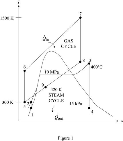
Determine the temperature of gas cycle at state 6.
Here, the temperature of gas cycle at state 5 is
Determine the rate of heat transfer into the gas turbine.
Here, the mass flow rate of air is
Determine the power rate for compressor of gas turbine.
Determine the temperature of gas cycle at state 8.
Here, the pressure of gas cycle at state 8 is
Determine the power rate for gas turbine of gas turbine.
Determine the net power output of the gas cycle.
Determine input work done per unit mass of the isentropic process for the steam cycle.
Here, the specific volume of the steam is
Determine the specific enthalpy at state 2 of the steam cycle.
Here, the specific enthalpy at the state 1 of the steam cycle is
Determine the quality at state 4 of the stream cycle.
Here, the specific entropy at state 4 is
Determine the specific enthalpy at state 4 of the steam cycle.
Here, the specific enthalpy of saturated liquid is
Write the expression for the steady-flow energy balance equation.
Here, the total energy rate of entering the system is
Substitute
Here, the temperature of gas cycle at state 8 is
Determine the power rate for gas turbine of steam cycle.
Here, the mass flow rate of the steam is
Determine the power rate of the isentropic process for the steam cycle.
Here, the mass flow rate of the steam is
Determine the net power output of the steam cycle.
Conclusion:
From the Table A-2, “Ideal-gas specific heats of various common gases”, obtain the value of specific heat of constant pressure and the ratio of specific heat at temperature of
Substitute 300 K for
Substitute
Substitute
Substitute 1500 K for
Substitute
Substitute 11547 kW for
From the Table A-4, “Saturated water-Pressure table”, obtain the value of the initial specific enthalpy at liquid state, specific volume at the liquid state, the specific entropy at liquid state, the specific enthalpy change upon vaporization at pressure, and the specific entropy change upon vaporization at pressure of 15 kPa as:
Substitute
Substitute
From the Table A-6, “Superheated water”, obtain the value of the specific enthalpy at state 3 and the specific entropy at state 3 at pressure of 10 MPa and temperature of
Substitute
Substitute 0.7528 for
Substitute
Thus, the mass flow rate of the steam is
Substitute
Substitute
Substitute 1384.013 kW for
(b)
The net work output of the combined cycle.
Answer to Problem 82P
The net work output of the combined cycle is
Explanation of Solution
Determine the net power output of combined cycle.
Conclusion:
Substitute 1371 kW for
Thus, the net work output of the combined cycle is
(c)
The thermal efficiency of the combined cycle.
Answer to Problem 82P
The thermal efficiency of the combined cycle is
Explanation of Solution
Determine the thermal efficiency of the combined cycle.
Conclusion:
Substitute 7819 kW for
Thus, the thermal efficiency of the combined cycle is
Want to see more full solutions like this?
Chapter 10 Solutions
EBK THERMODYNAMICS: AN ENGINEERING APPR


- Please do not use any AI tools to solve this question. I need a fully manual, step-by-step solution with clear explanations, as if it were done by a human tutor. No AI-generated responses, please.arrow_forwardPlease do not use any AI tools to solve this question. I need a fully manual, step-by-step solution with clear explanations, as if it were done by a human tutor. No AI-generated responses, please.arrow_forwardCE-112 please solve this problem step by step and give me the correct answerarrow_forward
- CE-112 please solve this problem step by step and give me the correct asnwerarrow_forwardthis is an old practice exam, the answer is Ax = -4, Ay = -12,Az = 32.5, Bx= 34, Bz = 5, By = 0 but how?arrow_forwardThis is an old practice exam, the answer is Ax = Az = 0, Ay = 2000, TDE = 4750, Cx = 2000, Cy = 2000, Cz = -800 but how?arrow_forward
- this is an old practice exam, the answer is Fmin = 290.5lb but howarrow_forwardThis is an exam review question. The answer is Pmin = 622.9 lb but whyarrow_forwardPlease do not use any AI tools to solve this question. I need a fully manual, step-by-step solution with clear explanations, as if it were done by a human tutor. No AI-generated responses, please.arrow_forward
- Please do not use any AI tools to solve this question. I need a fully manual, step-by-step solution with clear explanations, as if it were done by a human tutor. No AI-generated responses, please.arrow_forwardPlease do not use any AI tools to solve this question. I need a fully manual, step-by-step solution with clear explanations, as if it were done by a human tutor. No AI-generated responses, please.arrow_forwardThis is an old practice exam. Fce = 110lb and FBCD = 62 lb but whyarrow_forward
 Refrigeration and Air Conditioning Technology (Mi...Mechanical EngineeringISBN:9781305578296Author:John Tomczyk, Eugene Silberstein, Bill Whitman, Bill JohnsonPublisher:Cengage Learning
 Principles of Heat Transfer (Activate Learning wi...Mechanical EngineeringISBN:9781305387102Author:Kreith, Frank; Manglik, Raj M.Publisher:Cengage Learning