
Loose Leaf for Engineering Circuit Analysis Format: Loose-leaf
9th Edition
ISBN: 9781259989452
Author: Hayt
Publisher: Mcgraw Hill Publishers
expand_more
expand_more
format_list_bulleted
Concept explainers
Videos
Textbook Question
Chapter 10.7, Problem 14P
If superposition is used on the circuit of Fig. 10.30, find V1 with (a) only the 20∠0° mA source operating; (b) only the 50∠−90° mA source operating.
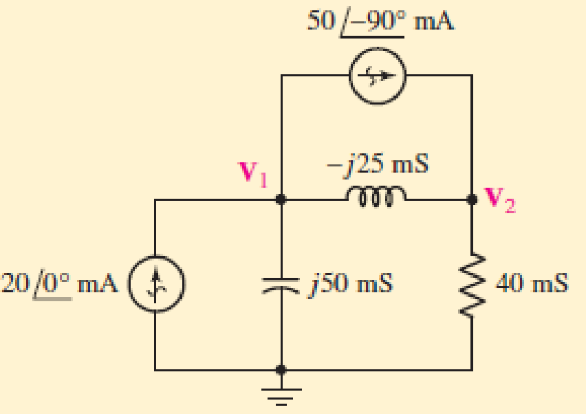
■ FIGURE 10.30
Expert Solution & Answer
Want to see the full answer?
Check out a sample textbook solution
Students have asked these similar questions
Example 1: There is a transfer function for a second-order system given as follows.
120
G(s)=
s²+12s+120
Find 5,,, T, T, T., and %OS.
5. Please sketch a root locus manually for the following system.
R(s) +
E(s)
C(s)
k(s + 1)
s² + 2s +2
Each branch in your root locus must be labeled with an arrow. Please answer the following
questions.
a. Is the closed-loop system stable as k is varying from 0 to co? Please find an answer to this
question via root locus.
b. What are finite zeros and poles? Are there infinite zeros? If so, how many?
-5. Draw the connection diagram for two parallel transformers with (A-A)
connected?
Chapter 10 Solutions
Loose Leaf for Engineering Circuit Analysis Format: Loose-leaf
Ch. 10.1 - Find the angle by which i1 lags v1 if v1 = 120...Ch. 10.2 - Determine values for A, B, C, and if 40 cos(100t ...Ch. 10.2 - Let vs = 40 cos 8000t V in the circuit of Fig....Ch. 10.3 - Prob. 4PCh. 10.3 - If the use of the passive sign convention is...Ch. 10.4 - Let = 2000 rad/s and t = 1 ms. Find the...Ch. 10.4 - Transform each of the following functions of time...Ch. 10.4 - In the circuit of Fig. 10.17, both sources operate...Ch. 10.5 - With reference to the network shown in Fig. 10.19,...Ch. 10.5 - In the frequency-domain circuit of Fig. 10.21,...
Ch. 10.5 - Determine the admittance (in rectangular form) of...Ch. 10.6 - Use nodal analysis on the circuit of Fig. 10.23 to...Ch. 10.6 - Use mesh analysis on the circuit of Fig. 10.25 to...Ch. 10.7 - If superposition is used on the circuit of Fig....Ch. 10.7 - Prob. 15PCh. 10.7 - Determine the current i through the 4 resistor of...Ch. 10.8 - Select some convenient reference value for IC in...Ch. 10 - Evaluate the following: (a) 5 sin (5t 9) at t =...Ch. 10 - (a) Express each of the following as a single...Ch. 10 - Prob. 3ECh. 10 - Prob. 4ECh. 10 - Prob. 5ECh. 10 - Calculate the first three instants in time (t 0)...Ch. 10 - (a) Determine the first two instants in time (t ...Ch. 10 - The concept of Fourier series is a powerful means...Ch. 10 - Household electrical voltages are typically quoted...Ch. 10 - Prob. 10ECh. 10 - Assuming there are no longer any transients...Ch. 10 - Calculate the power dissipated in the 2 resistor...Ch. 10 - Prob. 13ECh. 10 - Prob. 14ECh. 10 - Prob. 15ECh. 10 - Express the following complex numbers in...Ch. 10 - Prob. 17ECh. 10 - Prob. 18ECh. 10 - Evaluate the following, and express your answer in...Ch. 10 - Perform the indicated operations, and express the...Ch. 10 - Insert an appropriate complex source into the...Ch. 10 - For the circuit of Fig. 10.51, if is = 2 cos 5t A,...Ch. 10 - In the circuit depicted in Fig. 10.51, if is is...Ch. 10 - Employ a suitable complex source to determine the...Ch. 10 - Transform each of the following into phasor form:...Ch. 10 - Prob. 26ECh. 10 - Prob. 27ECh. 10 - The following complex voltages are written in a...Ch. 10 - Assuming an operating frequency of 50 Hz, compute...Ch. 10 - Prob. 30ECh. 10 - Prob. 31ECh. 10 - Prob. 32ECh. 10 - Assuming the passive sign convention and an...Ch. 10 - The circuit of Fig. 10.53 is shown represented in...Ch. 10 - (a) Obtain an expression for the equivalent...Ch. 10 - Determine the equivalent impedance of the...Ch. 10 - (a) Obtain an expression for the equivalent...Ch. 10 - Determine the equivalent admittance of the...Ch. 10 - Prob. 40ECh. 10 - Prob. 41ECh. 10 - Find V in Fig. 10.55 if the box contains (a) 3 in...Ch. 10 - Prob. 43ECh. 10 - Prob. 44ECh. 10 - Design a suitable combination of resistors,...Ch. 10 - Design a suitable combination of resistors,...Ch. 10 - For the circuit depicted in Fig. 10.58, (a) redraw...Ch. 10 - For the circuit illustrated in Fig. 10.59, (a)...Ch. 10 - Referring to the circuit of Fig. 10.59, employ...Ch. 10 - In the phasor-domain circuit represented by Fig....Ch. 10 - With regard to the two-mesh phasor-domain circuit...Ch. 10 - Employ phasor analysis techniques to obtain...Ch. 10 - Determine IB in the circuit of Fig. 10.62 if and ....Ch. 10 - Determine V2 in the circuit of Fig. 10.62 if and ....Ch. 10 - Employ phasor analysis to obtain an expression for...Ch. 10 - Determine the current ix in the circuit of Fig....Ch. 10 - Obtain an expression for each of the four...Ch. 10 - Determine the nodal voltages for the circuit of...Ch. 10 - Prob. 59ECh. 10 - Obtain an expression for each of the four mesh...Ch. 10 - Determine the individual contribution each current...Ch. 10 - Determine V1 and V2 in Fig. 10.68 if I1 = 333 mA...Ch. 10 - Prob. 63ECh. 10 - Obtain the Thvenin equivalent seen by the (2 j) ...Ch. 10 - The (2 j) impedance in the circuit of Fig. 10.69...Ch. 10 - With regard to the circuit depicted in Fig. 10.70,...Ch. 10 - Prob. 67ECh. 10 - Determine the individual contribution of each...Ch. 10 - Determine the power dissipated by the 1 resistor...Ch. 10 - The source Is in the circuit of Fig. 10.75 is...Ch. 10 - Prob. 72ECh. 10 - (a) Calculate values for IL, IR, IC, VL, VR, and...Ch. 10 - In the circuit of Fig. 10.77, (a) find values for...Ch. 10 - The voltage source Vs in Fig. 10.78 is chosen such...Ch. 10 - For the circuit shown in Fig. 10.79, (a) draw the...Ch. 10 - For the circuit shown in Fig. 10.80, (a) draw the...Ch. 10 - (a) Replace the inductor in the circuit of Fig....Ch. 10 - Design a purely passive network (containing only...
Knowledge Booster


Learn more about
Need a deep-dive on the concept behind this application? Look no further. Learn more about this topic, electrical-engineering and related others by exploring similar questions and additional content below.Similar questions
- HW_#6 HW_06.pdf EE 213-01 Assignments zm Rich LTI uah.instructure.com Z (MAE 272-01) (SP25) DYNAMICS b My Questions | bartleby ✓ Download → Info Page 1 > of 2 - ZOOM + 1) (5 pts) Note have to use nodal analysis at Vp and Vn. a) Determine Vout in the following ideal op-amp circuit. The power supplies supplying power to the op-amp have voltage values of ±15 volts (Vcc = +15 Volts, -VCC = -15Volts) b) Determine the value of RĘ that makes Vo, -15 Volts. c) What value of RF makes Vo = 0 Volts? out F out = 2V 1V 25K 10K 2V 1V 30K 100K RF 12K 12K + E น out E 2) (5 pts) Find Vout in the following circuit. Perform nodal analysis at nodes VN, VP and Va 20K Va 20K 10K 10K 1 V 2 V 5K Vout 15K Note: There is no restriction on the value for Vout for this problem. 3) (5 pts) For the Thevenin equivalent circuit shown, answer the following questions: 250 Ohms a 200 V ° b a) What load resistor results in maximum power delivered to that resistor? b) What is the maximum power delivered to the resistor in…arrow_forwardSuppose the Laplace transform of a causal signal x₁ (t) is given by X₁(s) s+2 s²+1 (a) What is the Fourier transform X₁ (w) of the signal? (b) Using the Laplace transform properties, find the Laplace transform of the following signal x2(t). x2(t) = e³ x₁(t−1)-4x₁(4) Note, you do not need to simplify the expression of X2(s). However, state whether it is possible to write X2(s) as a rational fraction (i.e. ratio of polynomials) in s.arrow_forwardConsider the following mechanical system. In the figure, y(t) denotes the displacement of the mass from its equilibrium position and u(t) denotes the force applied to the mass. k1 kz - y(t) -0000 0000 3 ► u(t) b a) Find the differential equation model of the system. b) Find the state-space model for the system. Write x, A, B, C and D clearly in your answer.arrow_forward
- See whole documentarrow_forwardC(s) a) Reduce the following system to a single transfer function G(s): R(s) G3(s) R(s) C(s) G1(s) G2(s) G4(s) b) If the input r(t) is a step signal, what will be the output C(s)? Hint: Move the block G₂(s).arrow_forwardConsider the following electrical system. In the figure, u(t) and y(t) denote the input and output voltages, respectively. Please note that y(t) is the voltage across the resistor. с u(t) +1 y(t) R 0000 a) Find the differential equation model of the system. b) Write the transfer function H(s) = Y(s) of the system. U(s) c) If u(t) = 1 volt, what will be the steady-state output voltage?arrow_forward
- Q1: A Moore model sequential network has one input (X) and two outputs (Z2 Z1). An output Z2 = 1 and Z1 =0 occurs every time the input sequence 110 is completed and An output Z2 = 0 and Z1 1 occurs every time the input sequence 010 is completed otherwise Z2 = 0 and Z1 =0. Overlap is not allowed. Use D flip-flops in your design: a) Sketch the state diagram with minimum number of states. b) Construct the state table. = c) Construct the state assigned table. d) Determine the next-state and output logic expressions. e) Sketch the logic circuit.arrow_forwardConsider the following system where two objects are separated by a thermal conductor with thermal resistance R = 1. The temperatures of the objects are denoted by T₁ (t) and T2(t) and their thermal capacities are C₁ = 1 and C2 = 2. Assume, quantities follow their respective SI units. T₁(+) C₁ = 1 12(+) C₂=2 R=1 |T,(0) = 20° -Insulator: no heat flow 5260033500 If the initial temperatures of the two objects are 20°C and 50°C respectively, what will be the steady-state values of the temperatures of these two objects? What is the impact of R in the steady-state value?arrow_forward1 ΚΩ N₁ m ZL (10+j4) ks2 178/0° V N2 -202 Ω Figure P11.31 Circuit for Problem 11.31.arrow_forward
- HW_#6 HW_06.pdf EE 213-01 Assignments zm Rich LTI uah.instructure.com Z (MAE 272-01) (SP25) DYNAMICS b My Questions | bartleby ✓ Download → Info Page 1 > of 2 - ZOOM + 1) (5 pts) Note have to use nodal analysis at Vp and Vn. a) Determine Vout in the following ideal op-amp circuit. The power supplies supplying power to the op-amp have voltage values of ±15 volts (Vcc = +15 Volts, -VCC = -15Volts) b) Determine the value of RĘ that makes Vo, -15 Volts. c) What value of RF makes Vo = 0 Volts? out F out = 2V 1V 25K 10K 2V 1V 30K 100K RF 12K 12K + E น out E 2) (5 pts) Find Vout in the following circuit. Perform nodal analysis at nodes VN, VP and Va 20K Va 20K 10K 10K 1 V 2 V 5K Vout 15K Note: There is no restriction on the value for Vout for this problem. 3) (5 pts) For the Thevenin equivalent circuit shown, answer the following questions: 250 Ohms a 200 V ° b a) What load resistor results in maximum power delivered to that resistor? b) What is the maximum power delivered to the resistor in…arrow_forwardA 30 kVA, single-phase transformer is rated 240/120 volts is connected as a 120 / 360 volt autotransformer. Determine the rating of the auotransformer.arrow_forwardI just want a human answerarrow_forward
arrow_back_ios
SEE MORE QUESTIONS
arrow_forward_ios
Recommended textbooks for you
 Introductory Circuit Analysis (13th Edition)Electrical EngineeringISBN:9780133923605Author:Robert L. BoylestadPublisher:PEARSON
 Delmar's Standard Textbook Of ElectricityElectrical EngineeringISBN:9781337900348Author:Stephen L. HermanPublisher:Cengage Learning
 Programmable Logic ControllersElectrical EngineeringISBN:9780073373843Author:Frank D. PetruzellaPublisher:McGraw-Hill Education
 Fundamentals of Electric CircuitsElectrical EngineeringISBN:9780078028229Author:Charles K Alexander, Matthew SadikuPublisher:McGraw-Hill Education
 Electric Circuits. (11th Edition)Electrical EngineeringISBN:9780134746968Author:James W. Nilsson, Susan RiedelPublisher:PEARSON
 Engineering ElectromagneticsElectrical EngineeringISBN:9780078028151Author:Hayt, William H. (william Hart), Jr, BUCK, John A.Publisher:Mcgraw-hill Education,
Introductory Circuit Analysis (13th Edition)
Electrical Engineering
ISBN:9780133923605
Author:Robert L. Boylestad
Publisher:PEARSON
Delmar's Standard Textbook Of Electricity
Electrical Engineering
ISBN:9781337900348
Author:Stephen L. Herman
Publisher:Cengage Learning
Programmable Logic Controllers
Electrical Engineering
ISBN:9780073373843
Author:Frank D. Petruzella
Publisher:McGraw-Hill Education
Fundamentals of Electric Circuits
Electrical Engineering
ISBN:9780078028229
Author:Charles K Alexander, Matthew Sadiku
Publisher:McGraw-Hill Education
Electric Circuits. (11th Edition)
Electrical Engineering
ISBN:9780134746968
Author:James W. Nilsson, Susan Riedel
Publisher:PEARSON
Engineering Electromagnetics
Electrical Engineering
ISBN:9780078028151
Author:Hayt, William H. (william Hart), Jr, BUCK, John A.
Publisher:Mcgraw-hill Education,
Nodal Analysis for Circuits Explained; Author: Engineer4Free;https://www.youtube.com/watch?v=f-sbANgw4fo;License: Standard Youtube License