
MECHANICS OF MATERIALS
10th Edition
ISBN: 2818440034374
Author: HIBBELER
Publisher: PEARSON
expand_more
expand_more
format_list_bulleted
Videos
Textbook Question
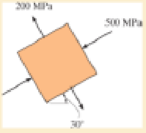
Chapter 10.7, Problem 10.92P
If the material is machine steel having a yield stress of σY = 750 MPa, determine the factor of safety with respect to yielding using the maximum distortion energy theory.
Expert Solution & Answer
Want to see the full answer?
Check out a sample textbook solution
Students have asked these similar questions
Can you help me with a matlab code? I am trying to plot the keplerian orbital elements over time. I would usually find the orbit using cartesian system and then transform into keplerian orbital elements. Is there a way to directly integrate keplerian orbital elements?
mylabmastering.pearson.com
Chapter 12 - Lecture Notes.pptx: (MAE 272-01) (SP25) DY...
P Pearson MyLab and Mastering
Scores
K
mylabmastering.pearson.com
Chapter 12 - Lecture Notes.pptx: (MAE 272-01) (SP25) DY...
P Pearson MyLab and Mastering
Mastering Engineering
Back to my courses
Course Home
Scores
Course Home
Chapter 10 Solutions
MECHANICS OF MATERIALS
Ch. 10.3 - Prove that the sum of the normal strains in...Ch. 10.3 - The state of strain at the point on the arm has...Ch. 10.3 - The state of strain at the point on the pin leaf...Ch. 10.3 - The state of strain at the point on the pin leaf...Ch. 10.3 - The state of strain at the point on the leaf of...Ch. 10.3 - Use the strain transformation equations and...Ch. 10.3 - Use the strain transformation equations and...Ch. 10.3 - Use the strain transformation equations to...Ch. 10.3 - Use the strain transformation equations to...Ch. 10.3 - Use the strain- transformation equations to...
Ch. 10.3 - Use the strain transformation equations to...Ch. 10.3 - Determine the equivalent state of strain on an...Ch. 10.3 - Determine the equivalent state of strain which...Ch. 10.3 - Use the strain transformation equations to...Ch. 10.3 - Determine the equivalent state of strain, which...Ch. 10.3 - Solve Prob.103 using Mohrs circle. 103. The state...Ch. 10.3 - using Mohrs circle. 103. The state of strain at...Ch. 10.3 - Solve Prob.105 using Mohrs circle. 105. The state...Ch. 10.3 - Solve Prob.108 using Mohrs circle 108. The state...Ch. 10.3 - using Mohrs circle. 106. The state of strain at a...Ch. 10.5 - The strain at point A on the bracket has...Ch. 10.5 - Determine (a) the principal strains at A, (b) the...Ch. 10.5 - Determine (a) the principal strains at A, in the...Ch. 10.5 - The following readings are obtained for each gage:...Ch. 10.5 - The following readings are obtained for each gage:...Ch. 10.5 - The following readings are obtained for each gage:...Ch. 10.5 - The following readings are obtained from each...Ch. 10.6 - For the case of plane stress, show that Hookes law...Ch. 10.6 - to develop the strain tranformation equations....Ch. 10.6 - Determine the modulus of elasticity and Polssons...Ch. 10.6 - If it is subjected to an axial load of 15 N such...Ch. 10.6 - If it has the original dimensions shown, determine...Ch. 10.6 - If it has the original dimensions shown, determine...Ch. 10.6 - A strain gage having a length of 20 mm Is attached...Ch. 10.6 - Determine the bulk modulus for each of the...Ch. 10.6 - The strain gage is placed on the surface of the...Ch. 10.6 - Determine the associated principal stresses at the...Ch. 10.6 - Determine the applied load P. What is the shear...Ch. 10.6 - If a load of P = 3 kip is applied to the A-36...Ch. 10.6 - The cube of aluminum is subjected to the three...Ch. 10.6 - The principal strains at a point on the aluminum...Ch. 10.6 - A uniform edge load of 500 lb/in. and 350 lb/in....Ch. 10.6 - Prob. 10.45PCh. 10.6 - A single strain gage, placed in the vertical plane...Ch. 10.6 - A single strain gage, placed in the vertical plane...Ch. 10.6 - If the material is graphite for which Eg = 800 ksi...Ch. 10.6 - Determine the normal stresses x and y in the plate...Ch. 10.6 - The steel shaft has a radius of 15 mm. Determine...Ch. 10.6 - Prob. 10.51PCh. 10.6 - The A-36 steel pipe is subjected to the axial...Ch. 10.6 - Air is pumped into the steel thin-walled pressure...Ch. 10.6 - Air is pumped into the steel thin-walled pressure...Ch. 10.6 - Prob. 10.55PCh. 10.6 - The thin-walled cylindrical pressure vessel of...Ch. 10.6 - The thin-walled cylindrical pressure vessel of...Ch. 10.6 - Prob. 10.58PCh. 10.7 - A material is subjected to plane stress. Express...Ch. 10.7 - A material is subjected to plane stress. Express...Ch. 10.7 - The yield stress for a zirconium-magnesium alloy...Ch. 10.7 - Solve Prob. 1061 using the maximum distortion...Ch. 10.7 - If a machine part is made of tool L2 steel and a...Ch. 10.7 - Solve Prob.1063 using the maximum distortion...Ch. 10.7 - Prob. 10.65PCh. 10.7 - If a shaft is made of a material for which y = 75...Ch. 10.7 - Solve Prob.1066 using the maximum shear stress...Ch. 10.7 - If the material is machine steel having a yield...Ch. 10.7 - The short concrete cylinder having a diameter of...Ch. 10.7 - Prob. 10.70PCh. 10.7 - The plate is made of Tobin bronze, which yields at...Ch. 10.7 - The plate is made of Tobin bronze, which yields at...Ch. 10.7 - An aluminum alloy is to be used for a solid drive...Ch. 10.7 - If a machine part is made of titanium (TI-6A1-4V)...Ch. 10.7 - The components of plane stress at a critical point...Ch. 10.7 - The components of plane stress at a critical point...Ch. 10.7 - The 304-stainless-steel cylinder has an inner...Ch. 10.7 - The 304-stainless-steel cylinder has an inner...Ch. 10.7 - If the 2-in diameter shaft is made from brittle...Ch. 10.7 - If the 2-in diameter shaft is made from cast iron...Ch. 10.7 - If Y = 50 ksi, determine the factor of safety for...Ch. 10.7 - Prob. 10.82PCh. 10.7 - If the yield stress for steel is Y = 36 ksi,...Ch. 10.7 - Prob. 10.84PCh. 10.7 - The state of stress acting at a critical point on...Ch. 10.7 - The shaft consists of a solid segment AB and a...Ch. 10.7 - The shaft consists of a solid segment AB and a...Ch. 10.7 - Prob. 10.88PCh. 10.7 - If Y = 50 ksi, determine the factor of safety for...Ch. 10.7 - The gas tank is made from A-36 steel and has an...Ch. 10.7 - The internal loadings at a critical section along...Ch. 10.7 - If the material is machine steel having a yield...Ch. 10.7 - If the material is machine steel having a yield...Ch. 10 - In the case of plane stress, where the in-plane...Ch. 10 - The plate is made of material having a modulus of...Ch. 10 - If the material is machine steel having a yield...Ch. 10 - Determine if yielding has occurred on the basis of...Ch. 10 - The 60 strain rosette is mounted on a beam. The...Ch. 10 - Use the strain transformation equations to...Ch. 10 - If the strain gages a and b at points give...Ch. 10 - Use the strain-transformation equations and...Ch. 10 - Use the strain transformation equations to...Ch. 10 - Specify the orientation of the corresponding...
Knowledge Booster


Learn more about
Need a deep-dive on the concept behind this application? Look no further. Learn more about this topic, mechanical-engineering and related others by exploring similar questions and additional content below.Similar questions
- K mylabmastering.pearson.com Chapter 12 - Lecture Notes.pptx: (MAE 272-01) (SP25) DY... P Pearson MyLab and Mastering Mastering Engineering Back to my courses Course Home Scores Course Homearrow_forwardChapter 12 - Lecture Notes.pptx: (MAE 272-01) (SP25) DY... Scoresarrow_forwardIn a single cylinder, four stroke, single acting gas engine, the cylinder diameter is 180 mm and the stroke is 350 mm . When running at 250 rpm , the mean area of the indicator diagram taken off the engine is 355 mm² , length of diagram 75 mm , scale of the indicator spring 90 kN/m sq per mm , and the number of explosions was counted to be 114 per minute. Calculate the indicated power. so i have already asked this question and got a good answer, however on step 4, i dont understand how they reached 18.43 KW. When i do the math provided, i get the answer 7195.566. Where am i going wrong? thanks StepsTo clarify how we determined the Indicated Power, I'll go over each step in detail. Step 1: Comprehending the Provided Information - Cylinder diameter (in meters) = 180 mm = 0.18 m - Stroke length (in meters) = 350 mm = 0.35 m - Engine speed = 250 rpm -Indicator diagram mean area = 355 mm² The diagram's length is 75 mm; its spring scale is 90 kN/m² per mm, or 90,000 N/m² per mm; and…arrow_forward
- In MATLAB, can you help me simulate an orbit under earth J2 perturbation with the Milankovich orbital elements? Also, can you check to see if they fit the Milankovich constraint equaiton?arrow_forward8. All of the members in the Warren truss of Figure 8 are of length 10 ft. Use the method of sections to determine the forces in the members BD,CD,CE. B A C D E F G 2000 lb 3000 lb 5000 lb Figure 8 Harrow_forwardAn acrobat is walking on a tightrope of length L =20.1 m attached to supports A and B at a distance of 20.0 m apart. The combined weight of the acrobat and his balancing pole is 900 N, and the friction between his shoes and the rope is large enough to prevent him from slipping. Neglecting the weight of the rope and any elastic deformation, determine the deflection (y) and the tension in portion AC and BC of the rope for values of x from 0.5 m to 10 m using 0.5 m increments. 1. Determine the maximum deflection (y) in the rope. 2. Plot tension of AC and BC vs. x (on the same plot with x on the x-axis). Turn in the plot and the table of x, TAC, and TBC (clearly label each). A C 20.0 m Barrow_forward
- 5. A 4000 lb block of concrete is attached by light inextensible cables to the truss in Figure 5. Determine the force in each member. State whether each member is in tension or compression. 3 ΘΑ D E cables all dimensions in feet.arrow_forwardA block hangs from the end of bar AB that is 5.80 meters long and connected to the wall in the xz plane. The bar is supported at end A by a ball joint such that it carries only a compressive force along its axis. The bar is supported in equilibrium at end B by cables BD and BC that connect to the xz plane at points C and D respectively with coordinates given in the figure. The z components of the moments exerted on the bar by these two cables sum to 0. The tension in cable BD is measured to be 210 Newtons. Input answers of zero as 0.00 to avoid an invalid answer due to significant figures. Determine the equivalent force and couple system acting at A that models only the forces exerted by both cables BD → and BC on the bar at B. Enter your results for Feq and Meg in Cartesian Components. Z D (c, 0, d) C (a, 0, b). X A f m B y cc 040 BY NC SA 2016 Eric Davishahl Values for dimensions on the figure are given in the following table. Note the figure may not be to scale. Variable Value a…arrow_forwardA bent tube is attached to a wall with brackets as shown. A force of F = 785 lb is applied to the end of the tube with direction indicated by the dimensions in the figure. a.) Determine the moment about point D due to the force F Enter your answer in Cartesian components with units of ft- lbs. b.) Determine the moment about a line (i.e. axis) running from D to C due to the force F. Enter your answer in Cartesian components with units of ft-lbs. 2013 Michael Swanbom x BY NC SA g Z h A с FK kaz Values for dimensions on the figure are given in the table below. Note the figure may not be to scale. Be sure to align your cartesian unit vectors with the coordinate axes shown in the figure. Variable Value α 4.84 in b 13.2 in с 12.5 in d 30.8 in h 18.7 in 22.0 in →> a. MD=( i+ k) ft- lb →> b. MDC = î + k) ft- lbarrow_forward
- F1 3 4 5 P F2 F2 Ꮎ e b 200 3 4 5 F1 The electric pole is subject to the forces shown. Force F1 245 N and force F2 = 310 N with an angle 0 = 20.2°. Determine the moment about point P of all forces. Take counterclockwise moments to be positive. = Values for dimensions on the figure are given in the following table. Note the figure may not be to scale. Variable Value a 2.50 m b 11.3 m с 13.0 m The moment about point P is m. N- If the moment about point P sums up to be zero. Determine the distance c while all other values remained the same. m.arrow_forwardF y b C 10 Z Determine the moment about O due to the force F shown, the magnitude of the force F = 76.0 lbs. Note: Pay attention to the axis. Values for dimensions on the figure are given in the following table. Note the figure may not be to scale. Variable Value a 1.90 ft b 2.80 ft с 2.60 ft d 2.30 ft Mo = lb + k) ft-arrow_forwardThe shelf bracket is subjected to the force F = 372 Newtons at an angle = 21.4°. Compute the moment (in N-m) that this force exerts about each of the two attachment points (screw locations in the figure). Take counterclockwise moments to be positive. a duk F -0 2013 cc Michael Swanbom BY NC O SA Values for dimensions on the figure are given in the following table. Note the figure may not be to scale. Variable Value a 43.0 cm b 32.3 cm с 2.58 cm The moment about the upper attachment point is N-m. The moment about the lower attachment point is N-m.arrow_forward
arrow_back_ios
SEE MORE QUESTIONS
arrow_forward_ios
Recommended textbooks for you
 Elements Of ElectromagneticsMechanical EngineeringISBN:9780190698614Author:Sadiku, Matthew N. O.Publisher:Oxford University Press
 Mechanics of Materials (10th Edition)Mechanical EngineeringISBN:9780134319650Author:Russell C. HibbelerPublisher:PEARSON
 Thermodynamics: An Engineering ApproachMechanical EngineeringISBN:9781259822674Author:Yunus A. Cengel Dr., Michael A. BolesPublisher:McGraw-Hill Education
 Control Systems EngineeringMechanical EngineeringISBN:9781118170519Author:Norman S. NisePublisher:WILEY
 Mechanics of Materials (MindTap Course List)Mechanical EngineeringISBN:9781337093347Author:Barry J. Goodno, James M. GerePublisher:Cengage Learning
 Engineering Mechanics: StaticsMechanical EngineeringISBN:9781118807330Author:James L. Meriam, L. G. Kraige, J. N. BoltonPublisher:WILEY
Elements Of Electromagnetics
Mechanical Engineering
ISBN:9780190698614
Author:Sadiku, Matthew N. O.
Publisher:Oxford University Press
Mechanics of Materials (10th Edition)
Mechanical Engineering
ISBN:9780134319650
Author:Russell C. Hibbeler
Publisher:PEARSON
Thermodynamics: An Engineering Approach
Mechanical Engineering
ISBN:9781259822674
Author:Yunus A. Cengel Dr., Michael A. Boles
Publisher:McGraw-Hill Education
Control Systems Engineering
Mechanical Engineering
ISBN:9781118170519
Author:Norman S. Nise
Publisher:WILEY
Mechanics of Materials (MindTap Course List)
Mechanical Engineering
ISBN:9781337093347
Author:Barry J. Goodno, James M. Gere
Publisher:Cengage Learning
Engineering Mechanics: Statics
Mechanical Engineering
ISBN:9781118807330
Author:James L. Meriam, L. G. Kraige, J. N. Bolton
Publisher:WILEY
Understanding Failure Theories (Tresca, von Mises etc...); Author: The Efficient Engineer;https://www.youtube.com/watch?v=xkbQnBAOFEg;License: Standard youtube license