
MECHANICS OF MATERIALS
10th Edition
ISBN: 2818440034374
Author: HIBBELER
Publisher: PEARSON
expand_more
expand_more
format_list_bulleted
Videos
Textbook Question
Chapter 10.5, Problem 10.22P
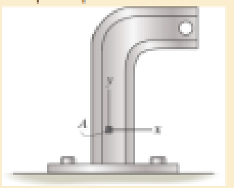
The strain at point A on the bracket has components εx = 300(10−6), εy = 550(10−6), γxy = −650(10−6), εz = 0, Determine (a) the principal strains at A in the x–y plane, (b) the maximum shear strain In the x-y plane, and (c) the absolute maximum shear strain.
Expert Solution & Answer

Learn your wayIncludes step-by-step video

schedule05:19
Students have asked these similar questions
Qu. 13 What are the indices for the Direction 2 indicated by vector in the following sketch?
Qu. 14 Determine the indices for the direction A and B shown in the following cubic unit cell.
please show all work step by step from material engineering
The thin-walled open cross section shown is transmitting torque 7. The angle of twist ₁ per unit length of each leg can be
determined separately using the equation
01
=
3Ti
GLIC
3
where G is the shear modulus, ₁ is the angle of twist per unit length, T is torque, and L is the length of the median line.
In this case, i = 1, 2, 3, and T; represents the torque in leg i. Assuming that the angle of twist per unit length for each
leg is the same, show that
T= Lic³ and Tmaz = G01 Cmax
Consider a steel section with Tallow = 12.40 kpsi.
C1
2 mm
L1
20 mm
C2
3 mm
L2
30 mm
C3
2 mm
L3
25 mm
Determine the torque transmitted by each leg and the torque transmitted by the entire section.
The torque transmitted by the first leg is |
N-m.
The torque transmitted by the second leg is
N-m.
The torque transmitted by the third leg is
N-m.
The torque transmitted by the entire section is
N-m.
Please help, make sure it's to box out and make it clear what answers go where...
Chapter 10 Solutions
MECHANICS OF MATERIALS
Ch. 10.3 - Prove that the sum of the normal strains in...Ch. 10.3 - The state of strain at the point on the arm has...Ch. 10.3 - The state of strain at the point on the pin leaf...Ch. 10.3 - The state of strain at the point on the pin leaf...Ch. 10.3 - The state of strain at the point on the leaf of...Ch. 10.3 - Use the strain transformation equations and...Ch. 10.3 - Use the strain transformation equations and...Ch. 10.3 - Use the strain transformation equations to...Ch. 10.3 - Use the strain transformation equations to...Ch. 10.3 - Use the strain- transformation equations to...
Ch. 10.3 - Use the strain transformation equations to...Ch. 10.3 - Determine the equivalent state of strain on an...Ch. 10.3 - Determine the equivalent state of strain which...Ch. 10.3 - Use the strain transformation equations to...Ch. 10.3 - Determine the equivalent state of strain, which...Ch. 10.3 - Solve Prob.103 using Mohrs circle. 103. The state...Ch. 10.3 - using Mohrs circle. 103. The state of strain at...Ch. 10.3 - Solve Prob.105 using Mohrs circle. 105. The state...Ch. 10.3 - Solve Prob.108 using Mohrs circle 108. The state...Ch. 10.3 - using Mohrs circle. 106. The state of strain at a...Ch. 10.5 - The strain at point A on the bracket has...Ch. 10.5 - Determine (a) the principal strains at A, (b) the...Ch. 10.5 - Determine (a) the principal strains at A, in the...Ch. 10.5 - The following readings are obtained for each gage:...Ch. 10.5 - The following readings are obtained for each gage:...Ch. 10.5 - The following readings are obtained for each gage:...Ch. 10.5 - The following readings are obtained from each...Ch. 10.6 - For the case of plane stress, show that Hookes law...Ch. 10.6 - to develop the strain tranformation equations....Ch. 10.6 - Determine the modulus of elasticity and Polssons...Ch. 10.6 - If it is subjected to an axial load of 15 N such...Ch. 10.6 - If it has the original dimensions shown, determine...Ch. 10.6 - If it has the original dimensions shown, determine...Ch. 10.6 - A strain gage having a length of 20 mm Is attached...Ch. 10.6 - Determine the bulk modulus for each of the...Ch. 10.6 - The strain gage is placed on the surface of the...Ch. 10.6 - Determine the associated principal stresses at the...Ch. 10.6 - Determine the applied load P. What is the shear...Ch. 10.6 - If a load of P = 3 kip is applied to the A-36...Ch. 10.6 - The cube of aluminum is subjected to the three...Ch. 10.6 - The principal strains at a point on the aluminum...Ch. 10.6 - A uniform edge load of 500 lb/in. and 350 lb/in....Ch. 10.6 - Prob. 10.45PCh. 10.6 - A single strain gage, placed in the vertical plane...Ch. 10.6 - A single strain gage, placed in the vertical plane...Ch. 10.6 - If the material is graphite for which Eg = 800 ksi...Ch. 10.6 - Determine the normal stresses x and y in the plate...Ch. 10.6 - The steel shaft has a radius of 15 mm. Determine...Ch. 10.6 - Prob. 10.51PCh. 10.6 - The A-36 steel pipe is subjected to the axial...Ch. 10.6 - Air is pumped into the steel thin-walled pressure...Ch. 10.6 - Air is pumped into the steel thin-walled pressure...Ch. 10.6 - Prob. 10.55PCh. 10.6 - The thin-walled cylindrical pressure vessel of...Ch. 10.6 - The thin-walled cylindrical pressure vessel of...Ch. 10.6 - Prob. 10.58PCh. 10.7 - A material is subjected to plane stress. Express...Ch. 10.7 - A material is subjected to plane stress. Express...Ch. 10.7 - The yield stress for a zirconium-magnesium alloy...Ch. 10.7 - Solve Prob. 1061 using the maximum distortion...Ch. 10.7 - If a machine part is made of tool L2 steel and a...Ch. 10.7 - Solve Prob.1063 using the maximum distortion...Ch. 10.7 - Prob. 10.65PCh. 10.7 - If a shaft is made of a material for which y = 75...Ch. 10.7 - Solve Prob.1066 using the maximum shear stress...Ch. 10.7 - If the material is machine steel having a yield...Ch. 10.7 - The short concrete cylinder having a diameter of...Ch. 10.7 - Prob. 10.70PCh. 10.7 - The plate is made of Tobin bronze, which yields at...Ch. 10.7 - The plate is made of Tobin bronze, which yields at...Ch. 10.7 - An aluminum alloy is to be used for a solid drive...Ch. 10.7 - If a machine part is made of titanium (TI-6A1-4V)...Ch. 10.7 - The components of plane stress at a critical point...Ch. 10.7 - The components of plane stress at a critical point...Ch. 10.7 - The 304-stainless-steel cylinder has an inner...Ch. 10.7 - The 304-stainless-steel cylinder has an inner...Ch. 10.7 - If the 2-in diameter shaft is made from brittle...Ch. 10.7 - If the 2-in diameter shaft is made from cast iron...Ch. 10.7 - If Y = 50 ksi, determine the factor of safety for...Ch. 10.7 - Prob. 10.82PCh. 10.7 - If the yield stress for steel is Y = 36 ksi,...Ch. 10.7 - Prob. 10.84PCh. 10.7 - The state of stress acting at a critical point on...Ch. 10.7 - The shaft consists of a solid segment AB and a...Ch. 10.7 - The shaft consists of a solid segment AB and a...Ch. 10.7 - Prob. 10.88PCh. 10.7 - If Y = 50 ksi, determine the factor of safety for...Ch. 10.7 - The gas tank is made from A-36 steel and has an...Ch. 10.7 - The internal loadings at a critical section along...Ch. 10.7 - If the material is machine steel having a yield...Ch. 10.7 - If the material is machine steel having a yield...Ch. 10 - In the case of plane stress, where the in-plane...Ch. 10 - The plate is made of material having a modulus of...Ch. 10 - If the material is machine steel having a yield...Ch. 10 - Determine if yielding has occurred on the basis of...Ch. 10 - The 60 strain rosette is mounted on a beam. The...Ch. 10 - Use the strain transformation equations to...Ch. 10 - If the strain gages a and b at points give...Ch. 10 - Use the strain-transformation equations and...Ch. 10 - Use the strain transformation equations to...Ch. 10 - Specify the orientation of the corresponding...
Additional Engineering Textbook Solutions
Find more solutions based on key concepts
How can work be held and supported in a lathe?
Degarmo's Materials And Processes In Manufacturing
A file that contains a Flash animation uses the __________ file extension. a. .class b. .swf c. .mp3 d. .flash
Web Development and Design Foundations with HTML5 (8th Edition)
Describe the three types of anomalies that can arise in a table and the negative consequences of each.
Modern Database Management
What is the importance of modeling in engineering? How are the mathematical models for engineering processes pr...
HEAT+MASS TRANSFER:FUND.+APPL.
Test Average and Grade Write a program that asks the user to enter five test scores. The program should display...
Starting Out with Programming Logic and Design (5th Edition) (What's New in Computer Science)
The current source in the circuit shown generates the current pulse
Find (a) v (0); (b) the instant of time gr...
Electric Circuits. (11th Edition)
Knowledge Booster


Learn more about
Need a deep-dive on the concept behind this application? Look no further. Learn more about this topic, mechanical-engineering and related others by exploring similar questions and additional content below.Similar questions
- The cylinder floats in the water and oil to the level shown. Determine the weight of the cylinder. (rho)o=910 kg/m^3arrow_forwardPlease help, make sure it's to box out and make it clear what answers go where..arrow_forwardPlease help, make sure it's to box out and make it clear what answers go where...arrow_forward
- Please help, make sure it's to box out and make it clear what answers go where...arrow_forwardA triangular distributed load of max intensity w acts on beam AB. The beam is supported by a pin at A and member CD, which is connected by pins at C and D respectively. Determine the largest load intensity, Wmax, that can be applied if the pin at D can support a maximum force of 18000 N. Also determine the reactions at A and C and express each answer in Cartesian components. Assume the masses of both beam and member ✓ are negligible. Dwas шал = A BY NC SA 2016 Eric Davishahl C D -a- Ур -b- X B W Values for dimensions on the figure are given in the following table. Note the figure may not be to scale. Variable Value a 6.6 m b 11.88 m C 4.29 m The maximum load intensity is = wmax N/m. The reaction at A is A = The reaction at C is = i+ Ĵ N. ĴN. 12 i+arrow_forwardThe beam is supported by a pin at B and a roller at C and is subjected to the loading shown with w =110 lb/ft, and F 205 lb. a.) If M = 2,590 ft-lb, determine the support reactions at B and C. Report your answers in both Cartesian components. b.) Determine the largest magnitude of the applied couple M for which the beam is still properly supported in equilibrium with the pin and roller as shown. 2013 Michael Swanbom CC BY NC SA M ру W B⚫ C F ka b Values for dimensions on the figure are given in the following table. Note the figure may not be to scale. Variable Value a 3.2 ft b 6.4 ft C 3 ft a.) The reaction at B is B = The reaction at C is C = ĵ lb. i+ Ĵ lb. b.) The largest couple that can be applied is M ft-lb. == i+arrow_forward
- The beam ABC has a mass of 79.0 kg and is supported by the rope BDC that runs through the frictionless pulley at D . The winch at C has a mass of 36.5 kg. The tension in the rope acts on the beam at points B and C and counteracts the moments due to the beam's weight (acting vertically at the midpoint of its length) and the weight of the winch (acting vertically at point C) such that the resultant moment about point A is equal to zero. Assume that rope segment CD is vertical and note that rope segment BD is NOT necessarily perpendicular to the beam. a.) Compute the tension in the rope. b.) Model the two forces the rope exerts on the beam as a single equivalent force and couple moment acting at point B. Enter your answer in Cartesian components. c.) Model the two forces the rope exerts on the beam as a single equivalent force (no couple) and determine the distance from A to the point along the beam where the equivalent force acts (measured parallel to the beam from A ). Enter your answer…arrow_forwardw1 Three distributed loads act on a beam as shown. The load between A and B increases linearly from 0 to a maximum intensity of w₁ = 12.8 lb/ft at point B. The load then varies linearly with a different slope to an intensity of w₂ = 17.1 lb/ft at C. The load intensity in section CD of the beam is constant at w3 10.2 lb/ft. For each load region, determine the resultant force and the location of its line of action (distance to the right of A for all cases). cc 10 BY NC SA 2016 Eric Davishahl = WI W2 W3 -b- C Values for dimensions on the figure are given in the following table. Note the figure may not be to scale. Variable Value a 4.50 ft b 5.85 ft с 4.28 ft The resultant load in region AB is FR₁ = lb and acts ft to the right of A. The resultant load in region BC is FR2 lb and acts = ft to the right of A. The resultant load in region CD is FR3 = lb and acts ft to the right of A.arrow_forwardThe T-shaped structure is embedded in a concrete wall at A and subjected to the force F₁ and the force-couple system F2 1650 N and M = 1,800 N-m at the locations shown. Neglect the weight of the structure in your calculations for this problem. = a.) Compute the allowable range of magnitudes for F₁ in the direction shown if the connection at A will fail when subjected to a resultant moment with a magnitude of 920 N- m or higher. b.) Focusing on the forces and igonoring given M for now. Using the value for F1, min that you calculated in (a), replace the two forces F₁ and F2 with a single force that has equivalent effect on the structure. Specify the equivalent →> force Feq in Cartesian components and indicate the horizontal distance from point A to its line of action (note this line of action may not intersect the structure). c.) Now, model the entire force system (F1,min, F2, and M) as a single force and couple acting at the junction of the horizontal and vertical sections of the…arrow_forward
- The heated rod from Problem 3 is subject to a volumetric heating h(x) = h0 x L in units of [Wm−3], as shown in the figure below. Under the heat supply the temperature of the rod changes along x with the temperature function T (x). The temperature T (x) is governed by the d following equations: − dx (q(x)) + h(x) = 0 PDE q(x) =−k dT dx Fourier’s law of heat conduction (4) where q(x) is the heat flux through the rod and k is the (constant) thermal conductivity. Both ends of the bar are in contact with a heat reservoir at zero temperature. Determine: 1. Appropriate BCs for this physical problem. 2. The temperature function T (x). 3. The heat flux function q(x). Side Note: Please see that both ends of bar are in contact with a heat reservoir at zero temperature so the boundary condition at the right cannot be du/dx=0 because its not thermally insulated. Thank youarrow_forwardThe elastic bar from Problem 1 spins with angular velocity ω about an axis, as shown in the figure below. The radial acceleration at a generic point x along the bar is a(x) = ω2x. Under this radial acceleration, the bar stretches along x with displacement function u(x). The displacement d u(x) is governed by the following equations: dx (σ(x)) + ρa(x) = 0 PDE σ(x) = E du dx Hooke’s law (2) where σ(x) is the axial stress in the rod, ρ is the mass density, and E is the (constant) Young’s modulus. The bar is pinned on the rotation axis at x = 0 and it is also pinned at x = L. Determine: 1. Appropriate BCs for this physical problem. 2. The displacement function u(x). 3. The stress function σ(x). SIDE QUESTION: I saw a tutor solve it before but I didn't understand why the tutor did not divide E under the second term (c1x) before finding u(x). The tutor only divided E under first term. please explain and thank youarrow_forwardcalculate the total power required to go 80 mph in a VW Type 2 Samba Bus weighing 2310 lbs. with a Cd of 0.35 and a frontal area of 30ft^2. Consider the coefficient of rolling resistance to be 0.018. What is the increase in power required to go the same speed if the weight is increased by 2205 pounds (the rated carrying capacity of the vehicle). If the rated power for the vehicle is 49 bhp, will the van be able to reach 80 mph at full carrying capacity?arrow_forward
arrow_back_ios
SEE MORE QUESTIONS
arrow_forward_ios
Recommended textbooks for you
 Elements Of ElectromagneticsMechanical EngineeringISBN:9780190698614Author:Sadiku, Matthew N. O.Publisher:Oxford University Press
 Mechanics of Materials (10th Edition)Mechanical EngineeringISBN:9780134319650Author:Russell C. HibbelerPublisher:PEARSON
 Thermodynamics: An Engineering ApproachMechanical EngineeringISBN:9781259822674Author:Yunus A. Cengel Dr., Michael A. BolesPublisher:McGraw-Hill Education
 Control Systems EngineeringMechanical EngineeringISBN:9781118170519Author:Norman S. NisePublisher:WILEY
 Mechanics of Materials (MindTap Course List)Mechanical EngineeringISBN:9781337093347Author:Barry J. Goodno, James M. GerePublisher:Cengage Learning
 Engineering Mechanics: StaticsMechanical EngineeringISBN:9781118807330Author:James L. Meriam, L. G. Kraige, J. N. BoltonPublisher:WILEY
Elements Of Electromagnetics
Mechanical Engineering
ISBN:9780190698614
Author:Sadiku, Matthew N. O.
Publisher:Oxford University Press
Mechanics of Materials (10th Edition)
Mechanical Engineering
ISBN:9780134319650
Author:Russell C. Hibbeler
Publisher:PEARSON
Thermodynamics: An Engineering Approach
Mechanical Engineering
ISBN:9781259822674
Author:Yunus A. Cengel Dr., Michael A. Boles
Publisher:McGraw-Hill Education
Control Systems Engineering
Mechanical Engineering
ISBN:9781118170519
Author:Norman S. Nise
Publisher:WILEY
Mechanics of Materials (MindTap Course List)
Mechanical Engineering
ISBN:9781337093347
Author:Barry J. Goodno, James M. Gere
Publisher:Cengage Learning
Engineering Mechanics: Statics
Mechanical Engineering
ISBN:9781118807330
Author:James L. Meriam, L. G. Kraige, J. N. Bolton
Publisher:WILEY
Lec21, Part 5, Strain transformation; Author: Mechanics of Materials (Libre);https://www.youtube.com/watch?v=sgJvz5j_ubM;License: Standard Youtube License