
Engineering Mechanics: Statics and Modified Mastering Engineering with eText and Access Card (14th Edition)
14th Edition
ISBN: 9780134229287
Author: Russell C. Hibbeler
Publisher: PEARSON
expand_more
expand_more
format_list_bulleted
Concept explainers
Videos
Textbook Question
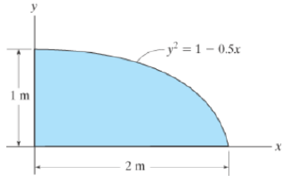
Chapter 10.3, Problem 8P
Determine the moment of inertia for the shaded area about the y axis.
Expert Solution & Answer
Want to see the full answer?
Check out a sample textbook solution
Students have asked these similar questions
Problem 9.5
9.5 A 1080-kg car is parked on a sloped street. The figure shows its wheels and the position of
its center of mass. The street is icy, and as a result the coefficient of static friction between
the car's tires and the street surface is μs = 0.2. Determine the steepest slope (in degrees
relative to the horizontal) at which the car could remain in equilibrium if
a. the brakes are applied to both its front and rear wheels;
b. the brakes are applied to the front (lower) wheels only.
Problem 9.5
1380 mm
532 mm
2370 mm
Can someone explain please with conversions
Correct Answer is written below. Detailed and complete fbd only please. I will upvote, thank you.
1: The assembly shown is composed of a rigid plank ABC, supported by hinge at A, spring at B and cable at C.The cable is attached to a frictionless pulley at D and rigidly supported at E. The cable is made of steel with E = 200,000MPa and cross-sectional area of 500 mm2. The details of pulley at D is shown. The pulley is supported by a pin, passingthough the pulley and attached to both cheeks. Note that E is directly above B.Given: H = 3 m; L1 = 2 m; L2 = 4 m; w = 12 kN/m; x:y = 3:4Spring Parameters:Wire diameter = 30 mmMean Radius = 90 mmNumber of turns = 12Modulus of Rigidity = 80 GPaAllowable stresses:Allowable shear stress of Pin at D = 85 MPaAllowable normal stress of cheek at D = 90MPaAllowable bearing stress of cheek at D = 110MPa1. Calculate the reaction of spring Band tension in cable at C.2. Calculate the vertical displacementat C and the required diameter ofpin at D.3.…
Chapter 10 Solutions
Engineering Mechanics: Statics and Modified Mastering Engineering with eText and Access Card (14th Edition)
Ch. 10.3 - Determine the moment of inertia of the shaded area...Ch. 10.3 - Determine the moment of inertia of the shaded area...Ch. 10.3 - Determine the moment of inertia of the shaded area...Ch. 10.3 - Determine the moment of inertia of the shaded area...Ch. 10.3 - Determine the moment of inertia about the x axis.Ch. 10.3 - Determine the moment of inertia about the y axis.Ch. 10.3 - Determine the moment of inertia for the shaded...Ch. 10.3 - Determine the moment of Inertia for the shaded...Ch. 10.3 - Determine the moment of inertia for the shaded...Ch. 10.3 - Determine the moment of inertia for the shaded...
Ch. 10.3 - Determine the moment of inertia for the shaded...Ch. 10.3 - Determine the moment of inertia for the shaded...Ch. 10.3 - Solve the problem in two ways, using rectangular...Ch. 10.3 - Determine the moment of inertia of the area about...Ch. 10.3 - Determine the moment of inertia for the shaded...Ch. 10.3 - Determine the moment of inertia for the shaded...Ch. 10.3 - Determine the moment of inertia about the x axis.Ch. 10.3 - Determine the moment of inertia about the y axis.Ch. 10.3 - Determine the moment of inertia for the shaded...Ch. 10.3 - Determine the moment of inertia for the shaded...Ch. 10.3 - Determine the moment of inertia for the shaded...Ch. 10.3 - Determine the moment of inertia for the shaded...Ch. 10.3 - Determine the moment of inertia for the shaded...Ch. 10.3 - Determine the moment of inertia for the shaded...Ch. 10.3 - Determine the moment of inertia for the shaded...Ch. 10.3 - Determine the moment of inertia for the shaded...Ch. 10.3 - Prob. 23PCh. 10.3 - Determine the moment of inertia for the shaded...Ch. 10.4 - Determine the moment of inertia of the beams...Ch. 10.4 - Determine the moment of inertia of the beams...Ch. 10.4 - Determine me moment of inertia of the...Ch. 10.4 - Determine the moment of inertia of the...Ch. 10.4 - Determine the moment of inertia of the composite...Ch. 10.4 - Determine the moment of inertia of the composite...Ch. 10.4 - The moment of inertia about the y axis is 264...Ch. 10.4 - Determine the location y of the centroid of the...Ch. 10.4 - Determine,y, which locates the centroidal axis x...Ch. 10.4 - Determine the moment of inertia for the beams...Ch. 10.4 - Determine the moment of inertia for the beams...Ch. 10.4 - Determine the moment of inertia Ix of the shaded...Ch. 10.4 - Determine the moment of inertia Ix of the shaded...Ch. 10.4 - Determine the moment of inertia of the beams...Ch. 10.4 - Determine, g, which locates the centroidal axis z...Ch. 10.4 - Determine the moment of inertia about the x axis.Ch. 10.4 - Prob. 37PCh. 10.4 - Determine the moment of inertia of the shaded area...Ch. 10.4 - Determine the moment of inertia of the shaded area...Ch. 10.4 - Prob. 40PCh. 10.4 - Prob. 41PCh. 10.4 - Determine the moment of inertia of the beams...Ch. 10.4 - Prob. 43PCh. 10.4 - Prob. 44PCh. 10.4 - Determine the distance x to the centroid C of the...Ch. 10.4 - Determine the moment of inertia for the shaded...Ch. 10.4 - Determine the moment of inertia for the shaded...Ch. 10.4 - Determine the moment of inertia of the...Ch. 10.4 - Determine the moment of inertia of the...Ch. 10.4 - Prob. 50PCh. 10.4 - Determine the moment of inertia for the beams...Ch. 10.4 - Determine the moment of inertia of the area about...Ch. 10.4 - Determine the moment of inertia of the area about...Ch. 10.7 - Determine the product of inertia of the thin strip...Ch. 10.7 - Determine the product of inertia of the shaded...Ch. 10.7 - Determine the product of inertia for the shaded...Ch. 10.7 - Determine the product of inertia of the shaded...Ch. 10.7 - Determine the product of inertia for the parabolic...Ch. 10.7 - Prob. 59PCh. 10.7 - Determine the product of inertia of the shaded...Ch. 10.7 - Prob. 61PCh. 10.7 - Prob. 62PCh. 10.7 - Prob. 63PCh. 10.7 - Determine the product of inertia for the beams...Ch. 10.7 - Determine the product of inertia tor the shaded...Ch. 10.7 - Determine the product of inertia of the cross...Ch. 10.7 - Determine the location (xy) to the centroid C of...Ch. 10.7 - For the calculation, assume all comers to be...Ch. 10.7 - Determine the moments of inertia Iu, Iv and the...Ch. 10.7 - Prob. 70PCh. 10.7 - using Mohrs circle Hint. To solve find the...Ch. 10.7 - Prob. 72PCh. 10.7 - using Mohrs circle.Ch. 10.7 - Prob. 74PCh. 10.7 - using Mohrs circle.Ch. 10.7 - Prob. 76PCh. 10.7 - using Mohrs circle.Ch. 10.7 - Prob. 78PCh. 10.7 - using Mohrs circle.Ch. 10.7 - Prob. 80PCh. 10.7 - Solve Prob. 10-80 using Mohrs circle.Ch. 10.7 - Prob. 82PCh. 10.7 - Solve Prob. 10-82 using Mohrs circle.Ch. 10.8 - Determine the moment of inertia of the thin ring...Ch. 10.8 - The material has a constant density .Ch. 10.8 - Determine the radius of gyration kx of the...Ch. 10.8 - Prob. 87PCh. 10.8 - Hint: For integration, use thin plate elements...Ch. 10.8 - The material has a constant density .Ch. 10.8 - Prob. 90PCh. 10.8 - Determine the moment of inertia Iy. The specific...Ch. 10.8 - Prob. 92PCh. 10.8 - Prob. 93PCh. 10.8 - The total mass of the solid is 1500 kg.Ch. 10.8 - The slender rods have a mass of 4 kg/ point A....Ch. 10.8 - and a 4-kg slender rod. Determine the radius of...Ch. 10.8 - The material has a density of 200kg/m3. Prob....Ch. 10.8 - Determine the location y of the center of mass G...Ch. 10.8 - Prob. 99PCh. 10.8 - The pendulum consists of a plate having a weight...Ch. 10.8 - 15 lb. and 20 lb, respectively, determine the mass...Ch. 10.8 - The density of the material is 7.85 Mg/m3.Ch. 10.8 - Prob. 103PCh. 10.8 - Determine its mass moment of inertia about the y...Ch. 10.8 - Prob. 105PCh. 10.8 - Prob. 106PCh. 10.8 - Prob. 107PCh. 10.8 - The thin plate has a mass of 12 kg/m2. Determine...Ch. 10.8 - The material has a density of 200kg/m3.Ch. 10.8 - Determine the moment of inertia for the shaded...Ch. 10.8 - Determine the moment of inertia for the shaded...Ch. 10.8 - Determine the area moment of inertia of the shaded...Ch. 10.8 - Prob. 4RPCh. 10.8 - Determine the area moment of inertia of the...Ch. 10.8 - Determine the product of inertia of the shaded...
Knowledge Booster


Learn more about
Need a deep-dive on the concept behind this application? Look no further. Learn more about this topic, mechanical-engineering and related others by exploring similar questions and additional content below.Similar questions
- Correct answer and complete fbd only. I will upvote. The compound shaft, composed of steel,aluminum, and bronze segments, carries the two torquesshown in the figure. If TC = 250 lb-ft, determine the maximumshear stress developed in each material (in ksi). The moduliof rigidity for steel, aluminum, and bronze are 12 x 106 psi, 4x 10⁶ psi, and 6 x 10⁶ psi, respectivelyarrow_forwardCan you explain the algebra steps that aren't shown but stated to be there, on how to get this equationarrow_forwardCorrect answer and complete fbd only. I will upvote. A flanged bolt coupling consists of two concentric rows of bolts. The inner row has 6 nos. of 16mm diameterbolts spaced evenly in a circle of 250mm in diameter. The outer row of has 10 nos. of 25 mm diameter bolts spaced evenly in a circle of 500mm in diameter. If the allowable shear stress on one bolt is 60 MPa, determine the torque capacity of the coupling. The Poisson’s ratio of the inner row of bolts is 0.2 while that of the outer row is 0.25 and the bolts are steel, E =200 GPa.arrow_forward
- Correct answer and complete fbd only. I will upvote. 10: The constant wall thickness of a steel tube with the cross sectionshown is 2 mm. If a 600-N-m torque is applied to the tube. Use G = 80 GPa forsteel.1. Find the shear stress (MPa) in the wall of the tube.2. Find the angle of twist, in degrees per meter of length.arrow_forwardCORRECT ANSWER WITH COMPLETE FBD ONLY. I WILL UPVOTE. A torque wrench is used to tighten the pipe shown.Dimensions: S1 = 400 mm; S2 = 250 mm; S3 = 100 mmModulus of Rigidity G = 78 GPa1. The diameter of the solid pipe is 20 mm. How much is themaximum force P (N) that can be applied based on theallowable shear stress of 60 MPa?2. For a hollow pipe with 50 mm outside diameter and is 6 mmthick, compute for the maximum force P (kN) that can beapplied such that the angle of twist at A does not exceed 5degrees.3. The torque applied to tighten the hollow pipe is 200 N-m.Given: Pipe outside diameter = 50 mm Pipe thickness = 6 mmSolve for the resulting maximum shear stress (MPa) in the pipe.arrow_forwardCorrect answer and complete fbd only. I will upvote. 6: The shaft carries a total torque T0 that is uniformly distributedover its length L. Determine the angle of twist (degrees) of the shaft in termsif T0 = 1.2 kN-m, L = 2 m, G = 80 GPa, and diameter = 120 mm.arrow_forward
- 2. Calculate the force in all members of the trusses shown using the method of joints. A 5525 lb C 3500 lb BY 14'-0" D 10'- 0" 6250 lb 10'- 0" Earrow_forwardCorrect answer and complete fbd only. I will upvote. 8: The steel rod fits loosely inside the aluminum sleeve. Both components are attached to a rigid wall at A andjoined together by a pin at B. Because of a slight misalignmentof the pre-drilled holes, the torque T0 = 750 N-m was appliedto the steel rod before the pin could be inserted into theholes. Determine the torque (N-m) in each component afterT0 was removed. Use G = 80 GPa for steel and G = 28 GPa foraluminumarrow_forwardCorrect answer and complete fbd only. I will upvote. 9: The two steel shafts, each with one end builtinto a rigid support, have flanges attached to their freeends. The flanges are to be bolted together. However,initially there is a 6⁰ mismatch in the location of the boltholes as shown in the figure. Determine the maximumshear stress(ksi) in each shaft after the flanges have beenbolted together. The shear modulus of elasticity for steelis 12 x 106 psi. Neglect deformations of the bolts and theflanges.arrow_forward
- Correct answer and complete fbd only. I will upvote. The tapered, wrought iron shaft carriesthe torque T = 2000 lb-in at its free end. Determine theangle of twist (degrees) of the shaft. Use G = 10 x 106psi for wrought ironarrow_forwardCorrect answer and complete fbd only. I will upvote. The compound shaft, consisting of steel and aluminumsegments, carries the two torques shown in the figure. Determine themaximum permissible value of T subject to the following designconditions: τst ≤ 83 MPa, τal ≤ 55 MPa, and θ ≤ 6⁰ (θ is the angle ofrotation of the free end). Use G =83 GPa for steel and G = 28 GPa foraluminum.arrow_forwardThe solid compound shaft, made of threedifferent materials, carries the two torques shown. Theshear moduli are 28 GPa for aluminum, 83 GPa for steel,and 35 GPa for bronze.1. Calculate the maximum shear stress (MPa) in eachmaterial.2. Find the angle of rotation (degrees) of the free endof the shaft.arrow_forward
arrow_back_ios
SEE MORE QUESTIONS
arrow_forward_ios
Recommended textbooks for you
 International Edition---engineering Mechanics: St...Mechanical EngineeringISBN:9781305501607Author:Andrew Pytel And Jaan KiusalaasPublisher:CENGAGE L
International Edition---engineering Mechanics: St...
Mechanical Engineering
ISBN:9781305501607
Author:Andrew Pytel And Jaan Kiusalaas
Publisher:CENGAGE L
moment of inertia; Author: NCERT OFFICIAL;https://www.youtube.com/watch?v=A4KhJYrt4-s;License: Standard YouTube License, CC-BY