
Engineering Mechanics: Statics and Modified Mastering Engineering with eText and Access Card (14th Edition)
14th Edition
ISBN: 9780134229287
Author: Russell C. Hibbeler
Publisher: PEARSON
expand_more
expand_more
format_list_bulleted
Concept explainers
Videos
Textbook Question
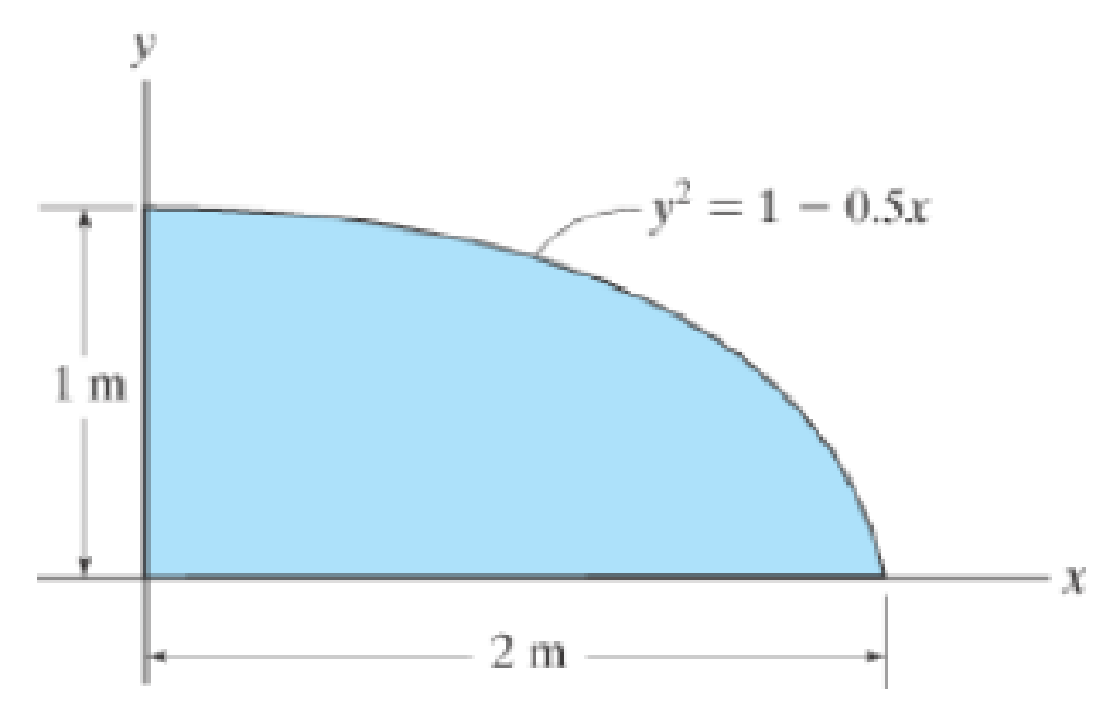
Chapter 10.3, Problem 7P
Determine the moment of inertia for the shaded area about the x axis.
Expert Solution & Answer
Want to see the full answer?
Check out a sample textbook solution
Students have asked these similar questions
handwritten-solutions, please!
No use chatgpt
Problem 6 (Optional, extra 6 points)
150 mm
150 mm
120 mm
80 mm
60 mm
PROBLEM 18.103
A 2.5 kg homogeneous disk of radius 80 mm rotates with an
angular velocity ₁ with respect to arm ABC, which is welded
to a shaft DCE rotating as shown at the constant rate
w212 rad/s. Friction in the bearing at A causes ₁ to
decrease at the rate of 15 rad/s². Determine the dynamic
reactions at D and E at a time when ₁ has decreased to
50 rad/s.
Answer:
5=-22.01 +26.8} N
E=-21.2-5.20Ĵ N
Chapter 10 Solutions
Engineering Mechanics: Statics and Modified Mastering Engineering with eText and Access Card (14th Edition)
Ch. 10.3 - Determine the moment of inertia of the shaded area...Ch. 10.3 - Determine the moment of inertia of the shaded area...Ch. 10.3 - Determine the moment of inertia of the shaded area...Ch. 10.3 - Determine the moment of inertia of the shaded area...Ch. 10.3 - Determine the moment of inertia about the x axis.Ch. 10.3 - Determine the moment of inertia about the y axis.Ch. 10.3 - Determine the moment of inertia for the shaded...Ch. 10.3 - Determine the moment of Inertia for the shaded...Ch. 10.3 - Determine the moment of inertia for the shaded...Ch. 10.3 - Determine the moment of inertia for the shaded...
Ch. 10.3 - Determine the moment of inertia for the shaded...Ch. 10.3 - Determine the moment of inertia for the shaded...Ch. 10.3 - Solve the problem in two ways, using rectangular...Ch. 10.3 - Determine the moment of inertia of the area about...Ch. 10.3 - Determine the moment of inertia for the shaded...Ch. 10.3 - Determine the moment of inertia for the shaded...Ch. 10.3 - Determine the moment of inertia about the x axis.Ch. 10.3 - Determine the moment of inertia about the y axis.Ch. 10.3 - Determine the moment of inertia for the shaded...Ch. 10.3 - Determine the moment of inertia for the shaded...Ch. 10.3 - Determine the moment of inertia for the shaded...Ch. 10.3 - Determine the moment of inertia for the shaded...Ch. 10.3 - Determine the moment of inertia for the shaded...Ch. 10.3 - Determine the moment of inertia for the shaded...Ch. 10.3 - Determine the moment of inertia for the shaded...Ch. 10.3 - Determine the moment of inertia for the shaded...Ch. 10.3 - Prob. 23PCh. 10.3 - Determine the moment of inertia for the shaded...Ch. 10.4 - Determine the moment of inertia of the beams...Ch. 10.4 - Determine the moment of inertia of the beams...Ch. 10.4 - Determine me moment of inertia of the...Ch. 10.4 - Determine the moment of inertia of the...Ch. 10.4 - Determine the moment of inertia of the composite...Ch. 10.4 - Determine the moment of inertia of the composite...Ch. 10.4 - The moment of inertia about the y axis is 264...Ch. 10.4 - Determine the location y of the centroid of the...Ch. 10.4 - Determine,y, which locates the centroidal axis x...Ch. 10.4 - Determine the moment of inertia for the beams...Ch. 10.4 - Determine the moment of inertia for the beams...Ch. 10.4 - Determine the moment of inertia Ix of the shaded...Ch. 10.4 - Determine the moment of inertia Ix of the shaded...Ch. 10.4 - Determine the moment of inertia of the beams...Ch. 10.4 - Determine, g, which locates the centroidal axis z...Ch. 10.4 - Determine the moment of inertia about the x axis.Ch. 10.4 - Prob. 37PCh. 10.4 - Determine the moment of inertia of the shaded area...Ch. 10.4 - Determine the moment of inertia of the shaded area...Ch. 10.4 - Prob. 40PCh. 10.4 - Prob. 41PCh. 10.4 - Determine the moment of inertia of the beams...Ch. 10.4 - Prob. 43PCh. 10.4 - Prob. 44PCh. 10.4 - Determine the distance x to the centroid C of the...Ch. 10.4 - Determine the moment of inertia for the shaded...Ch. 10.4 - Determine the moment of inertia for the shaded...Ch. 10.4 - Determine the moment of inertia of the...Ch. 10.4 - Determine the moment of inertia of the...Ch. 10.4 - Prob. 50PCh. 10.4 - Determine the moment of inertia for the beams...Ch. 10.4 - Determine the moment of inertia of the area about...Ch. 10.4 - Determine the moment of inertia of the area about...Ch. 10.7 - Determine the product of inertia of the thin strip...Ch. 10.7 - Determine the product of inertia of the shaded...Ch. 10.7 - Determine the product of inertia for the shaded...Ch. 10.7 - Determine the product of inertia of the shaded...Ch. 10.7 - Determine the product of inertia for the parabolic...Ch. 10.7 - Prob. 59PCh. 10.7 - Determine the product of inertia of the shaded...Ch. 10.7 - Prob. 61PCh. 10.7 - Prob. 62PCh. 10.7 - Prob. 63PCh. 10.7 - Determine the product of inertia for the beams...Ch. 10.7 - Determine the product of inertia tor the shaded...Ch. 10.7 - Determine the product of inertia of the cross...Ch. 10.7 - Determine the location (xy) to the centroid C of...Ch. 10.7 - For the calculation, assume all comers to be...Ch. 10.7 - Determine the moments of inertia Iu, Iv and the...Ch. 10.7 - Prob. 70PCh. 10.7 - using Mohrs circle Hint. To solve find the...Ch. 10.7 - Prob. 72PCh. 10.7 - using Mohrs circle.Ch. 10.7 - Prob. 74PCh. 10.7 - using Mohrs circle.Ch. 10.7 - Prob. 76PCh. 10.7 - using Mohrs circle.Ch. 10.7 - Prob. 78PCh. 10.7 - using Mohrs circle.Ch. 10.7 - Prob. 80PCh. 10.7 - Solve Prob. 10-80 using Mohrs circle.Ch. 10.7 - Prob. 82PCh. 10.7 - Solve Prob. 10-82 using Mohrs circle.Ch. 10.8 - Determine the moment of inertia of the thin ring...Ch. 10.8 - The material has a constant density .Ch. 10.8 - Determine the radius of gyration kx of the...Ch. 10.8 - Prob. 87PCh. 10.8 - Hint: For integration, use thin plate elements...Ch. 10.8 - The material has a constant density .Ch. 10.8 - Prob. 90PCh. 10.8 - Determine the moment of inertia Iy. The specific...Ch. 10.8 - Prob. 92PCh. 10.8 - Prob. 93PCh. 10.8 - The total mass of the solid is 1500 kg.Ch. 10.8 - The slender rods have a mass of 4 kg/ point A....Ch. 10.8 - and a 4-kg slender rod. Determine the radius of...Ch. 10.8 - The material has a density of 200kg/m3. Prob....Ch. 10.8 - Determine the location y of the center of mass G...Ch. 10.8 - Prob. 99PCh. 10.8 - The pendulum consists of a plate having a weight...Ch. 10.8 - 15 lb. and 20 lb, respectively, determine the mass...Ch. 10.8 - The density of the material is 7.85 Mg/m3.Ch. 10.8 - Prob. 103PCh. 10.8 - Determine its mass moment of inertia about the y...Ch. 10.8 - Prob. 105PCh. 10.8 - Prob. 106PCh. 10.8 - Prob. 107PCh. 10.8 - The thin plate has a mass of 12 kg/m2. Determine...Ch. 10.8 - The material has a density of 200kg/m3.Ch. 10.8 - Determine the moment of inertia for the shaded...Ch. 10.8 - Determine the moment of inertia for the shaded...Ch. 10.8 - Determine the area moment of inertia of the shaded...Ch. 10.8 - Prob. 4RPCh. 10.8 - Determine the area moment of inertia of the...Ch. 10.8 - Determine the product of inertia of the shaded...
Knowledge Booster


Learn more about
Need a deep-dive on the concept behind this application? Look no further. Learn more about this topic, mechanical-engineering and related others by exploring similar questions and additional content below.Similar questions
- Problem 1. Two uniform rods AB and CE, each of weight 3 lb and length 2 ft, are welded to each other at their midpoints. Knowing that this assembly has an angular velocity of constant magnitude c = 12 rad/s, determine: (1). the magnitude and direction of the angular momentum HD of the assembly about D. (2). the dynamic reactions (ignore mg) at the bearings at A and B. 9 in. 3 in. 03 9 in. 3 in. Answers: HD = 0.162 i +0.184 j slug-ft²/s HG = 2.21 k Ay =-1.1 lb; Az = 0; By = 1.1 lb; B₂ = 0.arrow_forwardProblem 5 (Optional, extra 6 points) A 6-lb homogeneous disk of radius 3 in. spins as shown at the constant rate w₁ = 60 rad/s. The disk is supported by the fork-ended rod AB, which is welded to the vertical shaft CBD. The system is at rest when a couple Mo= (0.25ft-lb)j is applied to the shaft for 2 s and then removed. Determine the dynamic reactions at C and D before and after the couple has been removed at 2 s. 4 in. C B Mo 5 in 4 in. Note: 2 rotating around CD induced by Mo is NOT constant before Mo is removed. and ₂ (two unknowns) are related by the equation: ₂ =0+ w₂t 3 in. Partial Answer (after Mo has been removed): C-7.81+7.43k lb D -7.81 7.43 lbarrow_forwardProblem 4. A homogeneous disk with radius and mass m is mounted on an axle OG with length L and a negligible mass. The axle is pivoted at the fixed-point O, and the disk is constrained to roll on a horizontal surface. The disk rotates counterclockwise at the constant rate o₁ about the axle. (mg must be included into your calculation) (a). Calculate the linear velocity of G and indicate it on the figure. (b). Calculate ₂ (constant), which is the angular velocity of the axle OG around the vertical axis. (c). Calculate the linear acceleration ā of G and indicate it on the figure. (d). Determine the force (assumed vertical) exerted by the floor on the disk (e). Determine the reaction at the pivot O. 1 Answers: N = mg +mr(r/L)² @² |j mr w IIG C R L i+ 2L =arrow_forward
- Problem 2. The homogeneous disk of weight W = 6 lb rotates at the constant rate co₁ = 16 rad/s with respect to arm ABC, which is welded to a shaft DCE rotating at the constant rate 2 = 8 rad/s. Assume the rod weight is negligible compared to the disk. Determine the dynamic reactions at D and E (ignore mg). Answers: D=-7.12ĵ+4.47k lb r-8 in. 9 in. B D E=-1.822+4.47 lb 9 in. E 12 in. 12 in. xarrow_forwardProblem 3. Each of the right angle rods has a mass of 120 g and is welded to the shaft, which rotates at a steady speed of 3600 rpm. Ignore the weight of the shaft AB. Find the bearing dynamic reaction at A due to the dynamic imbalance of the shaft. (ignore mgs) 100 N A 100 100 100 100 100 (Dimensions in millimeters) Answer: A=-8521-426j N Barrow_forwardThermodynamics. Need help solving this. Step by step with unitsarrow_forward
- Quiz/An eccentrically loaded bracket is welded to the support as shown in Figure below. The load is static. The weld size for weld w1 is h1 = 4mm, for w2 h2=6mm, and for w3 is h3 -6.5 mm. Determine the safety factor (S.f) for the welds. F=29 kN. Use an AWS Electrode type (E100xx). 163 mm 133 mm 140 mm w3 wiarrow_forwardE W X FO FB F10 F11 F12 Home Q: Consider the square of Figure below.The left face is maintained at 100°C and the top face at 500°C, while the other two faces are exposed to an environment at1 00°C, h=10 W/m². C and k=10 W/m.°C. The block is 1 m square. Compute the temperature of the various nodes as indicated in Figure below and the heat flows at the boundaries. T= 500°C Alt Explain to me in detail how to calculate the matrix in the Casio calculator type (fx-991ES plus) T= 100°C 1 2 4 7 1 m- 3 1 m 5 6 T= 100°C 8 9arrow_forwardWhich of the following sequences converge and which diverge? 1) a₁ = 2+(0.1)" 1-2n 2) a = 1+2n 1/n 3 16) a = n In n 17) an = n 1/n 1-5n4 3) an = n² +8n³ 18) an = √4" n n² -2n+1 n! 20) a = 4) an = 106 5) n-1 a₁ =1+(-1)" n+1 a-(+) (1-4) 6) = 7) a = 2n (-1)"+1 2n-1 21) an = n -A" 1/(Inn) 3n+1 22) a = 3n-1 1/n x" 23) a = , x>0 2n+1 3" x 6" 24) a = 2™" xn! 2n 8) a = n+1 πT 1 9) a„ = sin +- 2 n sin n 10) an = n 25) a = tanh(n) 26) a = 2n-1 27) a = tan(n) 1 -sin n n 11) a = 2" 28) an == " 1 + 2" In(n+1) 12) a = n (In n) 200 29) a = n 13) a = 8/n 14) a 1+ =(1+²)" 15) an 7 n = 10n 30) an-√√n²-n 1"1 31) adx nixarrow_forward
- A steel alloy contains 95.7 wt% Fe, 4.0 wt% W, and 0.3 wt% C.arrow_forwardb. A horizontal cantilever of effective length 3a, carries two concentrated loads W at a distance a from the fixed end and W' at a distance a from the free end. Obtain a formula for the maximum deflection due to this loading using Mohr's method. If the cantilever is 250 mm by 150mm steel I beam, 3 m long having a second moment of area I as 8500 cm4, determine W and W'to give a maximum deflection of 6 mm when the maximum stress due to bending is 90 Mpa. Take Young's modulus of material E as 185 Gpa.arrow_forwardWhich of the following sequences converge and which diverge? 1/n 1) a₁ = 2+(0.1)" 3 16) a = n 1-2n 2) a = In n 1+2n 17) an = 1/n n 1-5n4 3) an = n² +8n³ 18) an = √4" n n! n² -2n+1 20) a = 4) an = 106 5) n-1 a₁ =1+(-1)" n+1 a-(+) (1-4) 6) = 7) a = 2n (-1)"+1 2n-1 21) an = n -A" 1/(Inn) 3n+1 22) a = 3n-1 1/n x" 23) a = , x>0 2n+1 3" x 6" 24) a = 2™" xn! 2n 8) a = n+1 πT 1 9) a„ = sin +- 2 n sin n 10) an = n 25) a = tanh(n) 26) a = 2n-1 27) a = tan(n) 1 -sin n n 11) a = 2" 28) an == " 1 + 2" In(n+1) 12) a = n (In n) 200 29) a = n 13) a = 8/n 14) a 1+ =(1+²)" 15) an 7 n = 10n 30) an-√√n²-n 1"1 31) adx nixarrow_forward
arrow_back_ios
SEE MORE QUESTIONS
arrow_forward_ios
Recommended textbooks for you
 Elements Of ElectromagneticsMechanical EngineeringISBN:9780190698614Author:Sadiku, Matthew N. O.Publisher:Oxford University Press
 Mechanics of Materials (10th Edition)Mechanical EngineeringISBN:9780134319650Author:Russell C. HibbelerPublisher:PEARSON
 Thermodynamics: An Engineering ApproachMechanical EngineeringISBN:9781259822674Author:Yunus A. Cengel Dr., Michael A. BolesPublisher:McGraw-Hill Education
 Control Systems EngineeringMechanical EngineeringISBN:9781118170519Author:Norman S. NisePublisher:WILEY
 Mechanics of Materials (MindTap Course List)Mechanical EngineeringISBN:9781337093347Author:Barry J. Goodno, James M. GerePublisher:Cengage Learning
 Engineering Mechanics: StaticsMechanical EngineeringISBN:9781118807330Author:James L. Meriam, L. G. Kraige, J. N. BoltonPublisher:WILEY
Elements Of Electromagnetics
Mechanical Engineering
ISBN:9780190698614
Author:Sadiku, Matthew N. O.
Publisher:Oxford University Press
Mechanics of Materials (10th Edition)
Mechanical Engineering
ISBN:9780134319650
Author:Russell C. Hibbeler
Publisher:PEARSON
Thermodynamics: An Engineering Approach
Mechanical Engineering
ISBN:9781259822674
Author:Yunus A. Cengel Dr., Michael A. Boles
Publisher:McGraw-Hill Education
Control Systems Engineering
Mechanical Engineering
ISBN:9781118170519
Author:Norman S. Nise
Publisher:WILEY
Mechanics of Materials (MindTap Course List)
Mechanical Engineering
ISBN:9781337093347
Author:Barry J. Goodno, James M. Gere
Publisher:Cengage Learning
Engineering Mechanics: Statics
Mechanical Engineering
ISBN:9781118807330
Author:James L. Meriam, L. G. Kraige, J. N. Bolton
Publisher:WILEY
moment of inertia; Author: NCERT OFFICIAL;https://www.youtube.com/watch?v=A4KhJYrt4-s;License: Standard YouTube License, CC-BY