
Videos
Refer to the circuit shown in Figure 10–6. Assume that when the thermostat contact closes the compressor does not start, but the condenser fan and evaporator fan do start. When troubleshooting the circuit, a voltmeter connected across the compressor contactor coil CC indicates 0 volts. A voltmeter connected across the high-pressure switch indicates 0 volts, and a voltmeter placed across the thermostat contact indicates 0 volts. When the voltmeter is connected across the low-pressure switch it indicates 24 volts. Which of the following conditions could cause this problem?
a. The refrigerant pressure is too high.
b. The compressor contactor coil is open.
c. The refrigerant pressure is too low.
d. The thermostat contact is open.
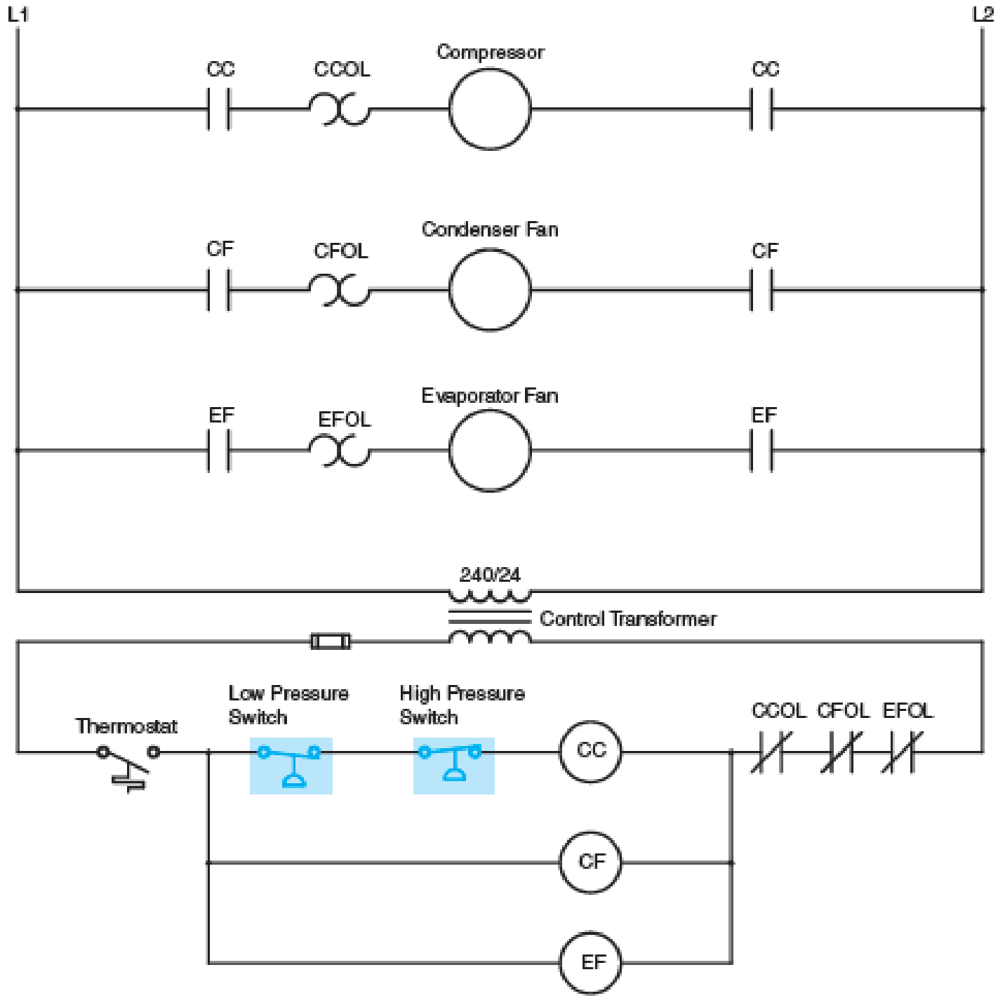
Fig. 10–6 Pressure switches are often used in air-conditioning circuits.
Want to see the full answer?
Check out a sample textbook solution
Chapter 10 Solutions
EBK ELECTRIC MOTOR CONTROL


- For a enahnced-type NMOS transistor with V₁=+1V and kn'(w/L)= 2 mA/V2, find the minimum VDs required to operate in the saturation region when VGS=+2 V. What is the corresponding value of ID?arrow_forward. Using Properties to find the Z-Transform including the region of convergence for x(n) = n (2)" cos(0.2π(n − 2))u(n − 1) - -arrow_forwardJ VDD M₁ In the circuit of figure shown below, determine the region of operation of M₁as Vigoes from VDD.to zero. (You may want to draw a plot or just explain by the range, remember the transistor is a PMOS) Assume VDD = 2.5 V and | VTH | = 0.4V. 5 + 1 Varrow_forward
- We wish to design the circuit of the figure shown below for a drain current of 1 mA (l=1mA). If W/L = 18/0.18, compute R1 and R2 such that the input impedance is at least 20 k. R₁ VDD = 1.8 V 500 Ω M₁ R₂arrow_forwardIn the figure shown below, what is the minimum allowable value of VDD if M₁ must not enter the triode region? Assume λ=0 (use ideal current formula that is not dependent on VDs) 1 V + RD VDD = 1.8 V T M 500 Ω 1 W 10 L = 0.18arrow_forwardCalculate the total charge stored in the channel of an NMOS device if Cox=10fF/um², w=10 µm, L=0.1 μm, and VGS-VTH=1 V. Assume VDs=0. (means there is no movement of electrons, all of them are piled up in the channel, we want to calculate the magnitude of electron charge |Q|)arrow_forward
- The first photo is question 1arrow_forwarda) Write down the order of the transfer function in each of the following cases. Assume that there are no terms in the numerator that will cancel terms in the denominator. 10 H(s) H(s) = s+1 5 (s+3)(s—. 4) 4s1 5 H(s) = H(s) - 83 +1 s27s 6 H(s) H(s) = s(s²+4s) 2s27s+1 84583882 +3s+2 H(s) 83 +8 s+1 = H(s) s34s26s+5 s52s4383 + 4s2 +5s +6arrow_forwardQuestion 5 ( A system is found to have zeros of -3 and poles of 4, and -2. The system also has a gain of 4. Write out the corresponding transfer function. Question 6. A system has a transfer function of What is the gain, K, of the system? Question 7 ( A system has a transfer function of H(s) - 4 8+5 H(s): = 4 8 +5 A step input of size 3 is applied to the system at time zero (Since we're dealing with transfer functions, x(0) is also zero at time zero). a) [10] What is the response ✗(s) of the system? b) [10] Derive the time dependent solution, x(t), of this responsearrow_forward
- Note: You might want to do the last question first because the last question asks you to write some python code to calculate the zeros and poles. You could use that code here to help you (except the first problem which you should be able to do by inspection alone) Find the poles and zeros for each of the following transfer functions 1. S+3 H(s) = 8 5 2. H(s): = s238 +1 s2 +48 +3 3. s(s+4) H(s) s3+2s23s 4. 82-586 H(s) = - 8382-68 5. H(s): = s2 +48 +3 s45836s2 - 6arrow_forwardWrite python program to plot the zeros and poles if a user provides the coefficients for the numerator and denominator of the transfer function. Since the zeros and poles can be complex, this plot is essentially and argand diagram, where the x axis is the real component and the y axis the imaginary component of a given zero or pole. Create a method called plot-poles zeros(num, den) which takes two lists containing the coefficients. Here is an example and the resulting plot. num [1, 3, 7] # yields zeros at -1.5 +/- 2.17945j den = [1, 4, 5, 3] # yields poles at -2.46557, -0.7672143 +/- 0.7925519j plot_poles_zeros(num, den) Imaginary Page 2 Pole-Zero Plot 3 Zeros × Poles 2 1 -2 1 * Real When you write your code you are only allowed to use the packages numpy and matplotlib. Make sure you label the axes, provide a legend and give a title to your plot (See the example plot). Hint: numpy has a method called roots. When given a list of numbers corresponding to the coefficients of a polynomial,…arrow_forwarda) [10] Compute the zeros and poles for the following transfer function: $2 +5s+6 H(s): s2 +3s+2 b) [10] Factor both polynomials in the numerator and denominator. What does this tell you about one of the poles and zeros you found in a)?arrow_forward

 Power System Analysis and Design (MindTap Course ...Electrical EngineeringISBN:9781305632134Author:J. Duncan Glover, Thomas Overbye, Mulukutla S. SarmaPublisher:Cengage Learning
 Electricity for Refrigeration, Heating, and Air C...Mechanical EngineeringISBN:9781337399128Author:Russell E. SmithPublisher:Cengage Learning