One end of a thin, uniform rod is connected to a frictionless hinge as shown in Figure 10.79 . The rod has a length of 0.8 m and a mass of 2 kg. It is held up in the horizontal position (θ = 90°) and then released. Calculate the angular velocity and angular acceleration of the rod at the following positions: (a) θ = 90°, (b) θ = 60°, and (c) θ = 0°. Figure 10.79 Problem 67.
One end of a thin, uniform rod is connected to a frictionless hinge as shown in Figure 10.79 . The rod has a length of 0.8 m and a mass of 2 kg. It is held up in the horizontal position (θ = 90°) and then released. Calculate the angular velocity and angular acceleration of the rod at the following positions: (a) θ = 90°, (b) θ = 60°, and (c) θ = 0°. Figure 10.79 Problem 67.
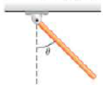
One end of a thin, uniform rod is connected to a frictionless hinge as shown in Figure 10.79. The rod has a length of 0.8 m and a mass of 2 kg. It is held up in the horizontal position (θ = 90°) and then released. Calculate the angular velocity and angular acceleration of the rod at the following positions: (a) θ = 90°, (b) θ = 60°, and (c) θ = 0°.
Figure 10.79
Problem 67.
Definition Definition Rate of change of angular velocity. Angular acceleration indicates how fast the angular velocity changes over time. It is a vector quantity and has both magnitude and direction. Magnitude is represented by the length of the vector and direction is represented by the right-hand thumb rule. An angular acceleration vector will be always perpendicular to the plane of rotation. Angular acceleration is generally denoted by the Greek letter α and its SI unit is rad/s 2 .
For each of the actions depicted below, a magnet and/or metal loop moves with velocity v→ (v→ is constant and has the same magnitude in all parts). Determine whether a current is induced in the metal loop. If so, indicate the direction of the current in the loop, either clockwise or counterclockwise when seen from the right of the loop. The axis of the magnet is lined up with the center of the loop. For the action depicted in (Figure 5), indicate the direction of the induced current in the loop (clockwise, counterclockwise or zero, when seen from the right of the loop). I know that the current is clockwise, I just dont understand why. Please fully explain why it's clockwise, Thank you
A planar double pendulum consists of two point masses \[m_1 = 1.00~\mathrm{kg}, \qquad m_2 = 1.00~\mathrm{kg}\]connected by massless, rigid rods of lengths \[L_1 = 1.00~\mathrm{m}, \qquad L_2 = 1.20~\mathrm{m}.\]The upper rod is hinged to a fixed pivot; gravity acts vertically downward with\[g = 9.81~\mathrm{m\,s^{-2}}.\]Define the generalized coordinates \(\theta_1,\theta_2\) as the angles each rod makes with thedownward vertical (positive anticlockwise, measured in radians unless stated otherwise).At \(t=0\) the system is released from rest with \[\theta_1(0)=120^{\circ}, \qquad\theta_2(0)=-10^{\circ}, \qquad\dot{\theta}_1(0)=\dot{\theta}_2(0)=0 .\]Using the exact nonlinear equations of motion (no small-angle or planar-pendulumapproximations) and assuming the rods never stretch or slip, determine the angle\(\theta_2\) at the instant\[t = 10.0~\mathrm{s}.\]Give the result in degrees, in the interval \((-180^{\circ},180^{\circ}]\).
What are the expected readings of the ammeter and voltmeter for the circuit in the figure below? (R = 5.60 Ω, ΔV = 6.30 V)
ammeter
I =
Chemistry: An Introduction to General, Organic, and Biological Chemistry (13th Edition)
Knowledge Booster
Learn more about
Need a deep-dive on the concept behind this application? Look no further. Learn more about this topic, physics and related others by exploring similar questions and additional content below.


 Principles of Physics: A Calculus-Based TextPhysicsISBN:9781133104261Author:Raymond A. Serway, John W. JewettPublisher:Cengage Learning
 Glencoe Physics: Principles and Problems, Student...PhysicsISBN:9780078807213Author:Paul W. ZitzewitzPublisher:Glencoe/McGraw-Hill
 Physics for Scientists and Engineers: Foundations...PhysicsISBN:9781133939146Author:Katz, Debora M.Publisher:Cengage Learning
 College PhysicsPhysicsISBN:9781305952300Author:Raymond A. Serway, Chris VuillePublisher:Cengage Learning
 Classical Dynamics of Particles and SystemsPhysicsISBN:9780534408961Author:Stephen T. Thornton, Jerry B. MarionPublisher:Cengage Learning
 University Physics Volume 1PhysicsISBN:9781938168277Author:William Moebs, Samuel J. Ling, Jeff SannyPublisher:OpenStax - Rice University