
(a)
The design of a plate girder for the given conditions, the selection of girder cross section and the required spacing of intermediate stiffeners by using LRFD.
Answer to Problem 10.7.8P
Four panels spaced at 58.25in.
Explanation of Solution
Given:
Span length
Uniformly distributed live load
Superimposed dead load
Concentrated dead load
Concentrated live load
Formula used:
h is the depth of web
Calculation:
Assume a girder weight of
Determine the factored loads:
The factored moment and shear are
Determine the overall depth:
Use the maximum permissible depth of 110 in.
Try
To determine the web thickness, first examine the limiting values of
For
Minimum
For
Minimum
Try a
Determine whether the web is slender:
Therefore, the web is slender.
Estimate required flange size:
Try a
Girder weight =
Compression flange:
Check flange local buckling (FLB):
Since
Compute the plate girder strength reduction factor:
Try a
Shear: At left end (end panel),
Required
From Table 3-17a in the Manual,
Use
This spacing will apply for the remaining distance to the centerline of the girder. This distance is
For a spacing a of 67 in., the number of panels is
Use 4 panels at
At
Required
For
Therefore, stiffeners are needed in middle
Conclusion:
Therefore, Use a
(b)
The size of intermediate and bearing stiffeners.
Answer to Problem 10.7.8P
2 PL
2 PL
Explanation of Solution
Given:
Span length
Uniformly distributed live load
Superimposed dead load
Concentrated dead load
Concentrated live load
Calculation:
Intermediate stiffener size:
Available width:
Try
To determine the required moment of inertia, use the conservative approximation from the User Note in AISC G2.3:
Try two
Length: From Figure 10.9 in the textbook (Steel design),
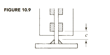
Assume a flange-to-web weld size of
Length =
Use two PL
Design the bearing stiffeners at the supports for a load of
Maximum stiffener width =
Try
Try two plates,
Bearing strength:
Compressive strength: The maximum permissible length of web is
Compute the radius of gyration about an axis along the middle of the web:
Compute the compressive strength:
Therefore,
Use 2 PL
Because there is a large difference between the reactions and the interior concentrated loads, use 2 PL
Conclusion:
Use two PL
(c)
The design of the all welds
Answer to Problem 10.7.8P
Explanation of Solution
Given:
Span length
Uniformly distributed live load
Superimposed dead load
Concentrated dead load
Concentrated live load
Calculation:
Design the flange-to-web welds.
The shear flow is
At the support,
Minimum weld size = 3/16 in. (AISC Table J2.4)
Minimum length =
Use 1.5 in.
Use E70 electrodes,
where D is weld size in sixteenths.
Try an
For two welds,
Weld strength =
Base metal shear yield strength (web plate controls) is
Shear rupture strength is
Weld strength controls.
For a 1.5-in. length,
Required spacing:
Since this is less than twice the length of the weld, use a continuous weld.
For
This occurs when
Maximum clear spacing: From AISC E6,
Maximum
For
Shear at first interior load, left of load, =
So maximum spacing will not be used in the first quarter of the span.
Spacing required at left side of first interior load is
Check middle fourth of span. Shear on right side of load is
Welds for intermediate stiffeners
Minimum weld size = 3/16in. (AISC Table J2.4)
Minimum length =
Use 1.5 in.
Use E70 electrodes,
where D is weld size in sixteenths.
Try
For four welds, the weld strength is
The base metal shear yield strength is
Shear rupture strength is
Weld strength controls.
For a 1.5-in. length,
The shear to be transferred is
A center-to-center spacing of 3 in. is equal to twice the length of the weld segment, so
either a continuous weld or an intermittent weld can be used. Use intermittent welds.
Maximum clear spacing: From AISC E6,
Maximum
Use
Welds for bearing stiffeners at the supports
Minimum weld size = 3/16in. (AISC Table J2.4)
Minimum length =
Use 1.5 in.
Use E70 electrodes,
where D is weld size in sixteenths.
Try
For four welds, the weld strength is
The base metal shear yield strength is
Shear rupture strength is
Weld strength controls.
For a 1.5-in. length,
The shear to be transferred is
Reaction
Use
Conclusion:
Use 3/16 in. continuous fillet welds for the first 20 ft,
Want to see more full solutions like this?
Chapter 10 Solutions
Steel Design (Activate Learning with these NEW titles from Engineering!)

- find SFD and BMDarrow_forwardThe data needed to answer this question is given by this link: https://docs.google.com/spreadsheets/d/1vzb03U7Uvzm7X-by3OchQNwYeREzbP6Z-xzZMP2tzNw/edit?usp=sharing if it is easier to make a copy of the data because it is on view only then feel free to do so.arrow_forwardThe data needed to answer this question is given in the following link (file is on view only so if you would like to make a copy to make it easier for yourself feel free to do so) https://docs.google.com/spreadsheets/d/1aV5rsxdNjHnkeTkm5VqHzBXZgW-Ptbs3vqwk0SYiQPo/edit?usp=sharingarrow_forward
- The benchmark is 00.00. The backsights are 6.00, 9.32 and 13.75 and 14.00 The foresights are 6.00, 9.00 and 3.22. What is the height of the instrument? H.I. - 100.00 - 124.85 - 43.07- 24.85arrow_forwardThe benchmark is 100.00. The backsights are 4.00, 6.32 and 12.75. The foresights are 6.00, 9.00 and 3.22. What is the elevation of the point? - 95.14 - 123.08 - 104.85 - 81.78arrow_forwardDetermine the stiffness matirx of the entire truss in Global co-ordinate system, clearly indicate the degrees of freedom numbers in the stiffness matrix.arrow_forward
- Determine the stiffness matrices of elements 2, 3 and 4 in the global co-ordinate system. Assume A=0.0015m2 and E=200GPa, indicate the degrees of freedom in all stiffness matricies.arrow_forwardA short plain concrete column with cross-section dimensions of 12 in x 12 in is to be constructed. If the compressive strength of the concrete (f’c) is 5000 psi, what is the maximum load that can be safely applied to the column? - 600 k - 950 k - 720 k - 347 karrow_forwardThe borrow pit has 2000 cyds of suitable fill. The fill required for the project is 1900 cyds. The swell factor is 10% and the shrinkage factor is 15%. How much more borrow do we need? Or is there extra? - 13 yards extra - 13 yards short - 200 yards extra - 161 yards shortarrow_forward
 Steel Design (Activate Learning with these NEW ti...Civil EngineeringISBN:9781337094740Author:Segui, William T.Publisher:Cengage Learning