
(a)
Find whether the statement “For normally consolidated clays
(a)
Answer to Problem 10.1P
The statement, “For normally consolidated clays
Explanation of Solution
According to Mohr-Coulomb failure criteria, the value of effective stress cohesion
The effective stress cohesion is approximated as 0 for normally consolidated clay.
Therefore, the statement, “For normally consolidated clays
(b)
Find whether the statement “Peak friction angle cannot be less than the ultimate friction angle” is true or false.
(b)
Answer to Problem 10.1P
The statement, “Peak friction angle cannot be less than the ultimate friction angle” is true.
Explanation of Solution
When the load is applying on a dense sand, the resisting shear stress increases with shear displacement until it attains a failure stress of
The shear stress gradually decreases with increases of shear displacement after reaches the failure stress. The continuous increase of shear displacement finally attains a constant value, then it is called ultimate shear strength.
Express the peak shear strength as follows:
Find the peak friction angle
Express the ultimate shear strength as follows:
Find the ultimate friction angle
Refer to Figure 10.6, “Determination of shear strength parameters for a dry sand using the results of direct shear stress” in the textbook.
From the Figure 10.6, the peak friction angle
The statement, “Peak friction angle cannot be less than the ultimate friction angle” is true.
(c)
Find whether the statement “The stress strain plot of a dense sand is similar in shape to that of a normally consolidated clay” is true or false.
(c)
Answer to Problem 10.1P
The statement, “The stress strain plot of a dense sand is similar in shape to that of a normally consolidated clay” is false.
Explanation of Solution
Sketch the stress-strain relationship for loose and dense sand as shown in Figure 1.
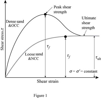
Refer to figure 1
The stress-strain curve for the loose sand is same as that of the normally consolidated clay.
The stress-strain curve for the dense sand is same as that of the over consolidated clay.
The statement, “The stress strain plot of a dense sand is similar in shape to that of a normally consolidated clay” is false.
(d)
Find whether the statement “Sensitivity of a clay can be less than one” is true or false.
(d)
Answer to Problem 10.1P
The statement, “Sensitivity of a clay can be less than one” is false.
Explanation of Solution
The sensitivity of clays is defined as the ratio of the unconfined compressive strength of clay in undisturbed to remoulded state.
The sensitivity of clay varies from 1 or
The statement, “Sensitivity of a clay can be less than one” is false.
(e)
Find whether the statement “
(e)
Answer to Problem 10.1P
The statement, “
Explanation of Solution
In consolidated undrained test, the shear strength parameters for over consolidated clay based on effective stress c and
In an unconsolidated undrained test, the failure envelope for the total stress lies on the horizontal line.
Hence,
The statement, “
Want to see more full solutions like this?
Chapter 10 Solutions
EBK FUNDAMENTALS OF GEOTECHNICAL ENGINE

- 15'-0" 15'-0" Architect specifications: 1) Superimposed dead load (including finishes, partition, mep etc) for each floor are shown next page. 2) The facade weight is 200 plf and it's all around the building, the parapet weight at the roofs is 100 plf. Don't forget to add these loads at the perimeter beams. 3) Wind Load is 30 psf 4) Use steel or LVL for beams, TJI of common wood for joists. 5) Submit your calc package by Sunday May 11th ALL STRUCTURAL ITEMS IN RED ARE PART OF THE GRAVITY SYSTEM ALL STRUCTURAL ITEMS IN BLUE ARE PART OF THE LATERAL SYSTEM I 10'-0" 2 10'-0" 10'-0" B I I I LAYOUR FOR OFFICES Things Required Dead and Live Load Schedule Gravity design for office floor - Load calculations (DL + LL + facade load if on perimeter) Beam sizing Joist spacing/type (TJI or LVL) Provide calculations for: Reaction forces Maximum moments Shear • Beam sizes (steel or LVL) Key Map of elements (your office layout plan with beam/joist marks) Iarrow_forwardplease solve the problem in the picture make sure you show all of your work, thank you so much for your help!arrow_forwardPlease solve the question in the picture make sure you show all of your work and show every step you do please. Thank you so much for your help!arrow_forward
- Please answer the question in the picture. solve for the ground level and also for the 2nd level please. Make sure to show all of your work. Thank you for your help!arrow_forwardQ3: Assuming the length of all vehicles is 6 m and the road length is 300 m, determine: SMS, TMS, Density, average spacings between vehicles and average headway at A- A section. 50 kph Veh 4 70 m 40 kph Veh 3 60 m 30 kph Veh 2 20m 25 kph A Veh 1 Traffic direction A (40 marks)arrow_forwardThe drainage system shown in fig 14.35 is designed to collect the stormwater from 3 atreas The areas runoof coefficients and overland flow times are as follows The rainfall intensity i (mm/h) as a function of rainfall duration t(min) is i =1.12/t+110 The flow time in sewer 1-2 is 2min and in sewer 2-3 is 2.5 minarrow_forward
- Please answer the question from the picture, show each step and explain please. Thank you so mucharrow_forwardFigure 1 shows the plan view of an Exhibition Hall with dimensions L1 x L2. The structure is to be constructed in a coastal region which will be exposed to mostly mild environmental conditions and should provide a 1.5-hour fire resistance. It is known that the underlying foundation soil contains sulphate and other organic compounds. The layout of the structure consists of portal frames which are spaced evenly along the L2 direction. The frames are to support a slab of thickness (t) that will cover the full area of the hall plan. The dead and live loads applied on the slab are G and Q (kPa), respectively.arrow_forwardA sample of Achilles saturated with water has a mass of 1710 g. After heating in an oven, a constant mass of 1815 g is obtained. The density of solid Achilles seeds is 2.78 g/cm3. We are asked to calculate: a) The water content and void ratio b) The porosity and specific gravity of the clayey soil c) The wet density of the clayey soil, the corresponding dry density and dry densityarrow_forward
- 8. A prestressed concrete beam is subjected to the following stress distributions: Pi is the initial prestressing force, Pe is the effective prestressing force, M, is the bending moment due to self- weight, Ma and M, are the dead load and live load bending moment, respectively. The concrete has the following properties: fr = 6000 psi and fri = 4200 psi +250 -85 -2500 +550 Pe+ Mo+Ma+Mi P alone P₁+ Mo -2450 -3500 Stress at midspan +210 +250 P, alone Pe alone -2500 -3500 Stress at ends Using Table 22.1, evaluate whether the stresses at the center of the span and the end of the span comply with the permissible stress limits. The beam is classified as U-class. Provide justifications for each condition listed in the table. Note: Calculated stresses are to be taken from the above diagram, and permissible stresses are to be calculated using Table 22.1. Compressive stresses immediately after transfer Tensile stresses immediately after transfer Compressive stresses under sustained and total…arrow_forward10. A short column is subjected to an eccentric loading. The axial load P = 1000 kips and the eccentricity e = 12 in. The material strengths are fy = 60 ksi and f = 6000 psi. The Young's modulus of steel is 29000 ksi. (a) Fill in the blanks in the interaction diagram shown below. (2pts each, 10pt total) Po Pn (1) failure range H 3" 30" Ast 6 No. 10 bars = P 22" I e H 3" (4) e = e small Load path for given e Radial lines show constant (2) eb (3) e large failure range Mn (5) e= Mo (b) Compute the balanced failure point, i.e., P and Mb.arrow_forwardNo chatgpt plsarrow_forward
 Principles of Geotechnical Engineering (MindTap C...Civil EngineeringISBN:9781305970939Author:Braja M. Das, Khaled SobhanPublisher:Cengage Learning
 Fundamentals of Geotechnical Engineering (MindTap...Civil EngineeringISBN:9781305635180Author:Braja M. Das, Nagaratnam SivakuganPublisher:Cengage Learning
 Principles of Foundation Engineering (MindTap Cou...Civil EngineeringISBN:9781305081550Author:Braja M. DasPublisher:Cengage Learning
 Principles of Foundation Engineering (MindTap Cou...Civil EngineeringISBN:9781337705028Author:Braja M. Das, Nagaratnam SivakuganPublisher:Cengage Learning