
Concept explainers
Videos
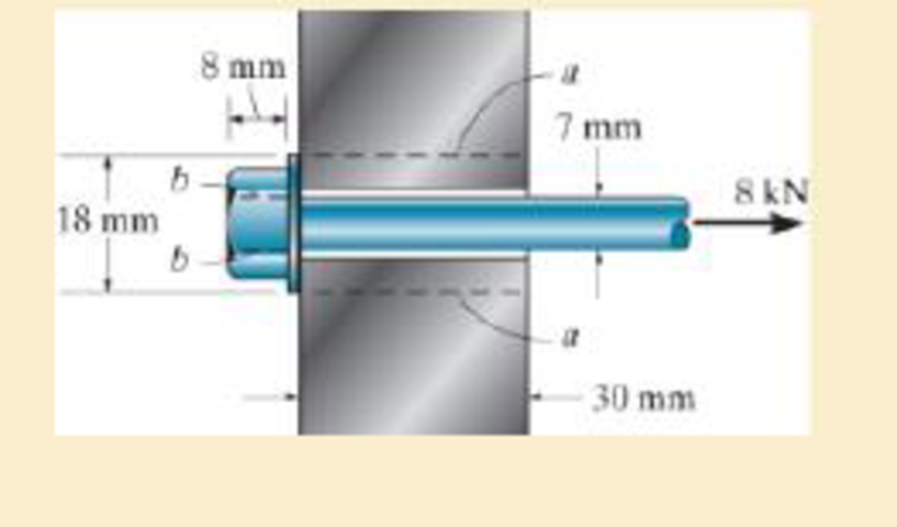
The long bolt passes through the 30-mm-thick plate. If the force in the bolt shank is 8 kN, determine the average normal stress in the shank, the average shear stress along the cylindrical area of the plate defined by the section lines a–a, and the average shear stress in the bolt head along the cylindrical area defined by the section lines b–b.

Trending nowThis is a popular solution!

Chapter 1 Solutions
MECHANICS OF MATERIALS
Additional Engineering Textbook Solutions
Starting Out with Python (4th Edition)
Automotive Technology: Principles, Diagnosis, And Service (6th Edition) (halderman Automotive Series)
Management Information Systems: Managing The Digital Firm (16th Edition)
Java How to Program, Early Objects (11th Edition) (Deitel: How to Program)
Modern Database Management
Thermodynamics: An Engineering Approach


- Correct answer and complete fbd only. I will upvote. The compound shaft, composed of steel,aluminum, and bronze segments, carries the two torquesshown in the figure. If TC = 250 lb-ft, determine the maximumshear stress developed in each material (in ksi). The moduliof rigidity for steel, aluminum, and bronze are 12 x 106 psi, 4x 10⁶ psi, and 6 x 10⁶ psi, respectivelyarrow_forwardCan you explain the algebra steps that aren't shown but stated to be there, on how to get this equationarrow_forwardCorrect answer and complete fbd only. I will upvote. A flanged bolt coupling consists of two concentric rows of bolts. The inner row has 6 nos. of 16mm diameterbolts spaced evenly in a circle of 250mm in diameter. The outer row of has 10 nos. of 25 mm diameter bolts spaced evenly in a circle of 500mm in diameter. If the allowable shear stress on one bolt is 60 MPa, determine the torque capacity of the coupling. The Poisson’s ratio of the inner row of bolts is 0.2 while that of the outer row is 0.25 and the bolts are steel, E =200 GPa.arrow_forward
- Correct answer and complete fbd only. I will upvote. 10: The constant wall thickness of a steel tube with the cross sectionshown is 2 mm. If a 600-N-m torque is applied to the tube. Use G = 80 GPa forsteel.1. Find the shear stress (MPa) in the wall of the tube.2. Find the angle of twist, in degrees per meter of length.arrow_forwardCORRECT ANSWER WITH COMPLETE FBD ONLY. I WILL UPVOTE. A torque wrench is used to tighten the pipe shown.Dimensions: S1 = 400 mm; S2 = 250 mm; S3 = 100 mmModulus of Rigidity G = 78 GPa1. The diameter of the solid pipe is 20 mm. How much is themaximum force P (N) that can be applied based on theallowable shear stress of 60 MPa?2. For a hollow pipe with 50 mm outside diameter and is 6 mmthick, compute for the maximum force P (kN) that can beapplied such that the angle of twist at A does not exceed 5degrees.3. The torque applied to tighten the hollow pipe is 200 N-m.Given: Pipe outside diameter = 50 mm Pipe thickness = 6 mmSolve for the resulting maximum shear stress (MPa) in the pipe.arrow_forwardCorrect answer and complete fbd only. I will upvote. 6: The shaft carries a total torque T0 that is uniformly distributedover its length L. Determine the angle of twist (degrees) of the shaft in termsif T0 = 1.2 kN-m, L = 2 m, G = 80 GPa, and diameter = 120 mm.arrow_forward
- 2. Calculate the force in all members of the trusses shown using the method of joints. A 5525 lb C 3500 lb BY 14'-0" D 10'- 0" 6250 lb 10'- 0" Earrow_forwardCorrect answer and complete fbd only. I will upvote. 8: The steel rod fits loosely inside the aluminum sleeve. Both components are attached to a rigid wall at A andjoined together by a pin at B. Because of a slight misalignmentof the pre-drilled holes, the torque T0 = 750 N-m was appliedto the steel rod before the pin could be inserted into theholes. Determine the torque (N-m) in each component afterT0 was removed. Use G = 80 GPa for steel and G = 28 GPa foraluminumarrow_forwardCorrect answer and complete fbd only. I will upvote. 9: The two steel shafts, each with one end builtinto a rigid support, have flanges attached to their freeends. The flanges are to be bolted together. However,initially there is a 6⁰ mismatch in the location of the boltholes as shown in the figure. Determine the maximumshear stress(ksi) in each shaft after the flanges have beenbolted together. The shear modulus of elasticity for steelis 12 x 106 psi. Neglect deformations of the bolts and theflanges.arrow_forward
- Correct answer and complete fbd only. I will upvote. The tapered, wrought iron shaft carriesthe torque T = 2000 lb-in at its free end. Determine theangle of twist (degrees) of the shaft. Use G = 10 x 106psi for wrought ironarrow_forwardCorrect answer and complete fbd only. I will upvote. The compound shaft, consisting of steel and aluminumsegments, carries the two torques shown in the figure. Determine themaximum permissible value of T subject to the following designconditions: τst ≤ 83 MPa, τal ≤ 55 MPa, and θ ≤ 6⁰ (θ is the angle ofrotation of the free end). Use G =83 GPa for steel and G = 28 GPa foraluminum.arrow_forwardThe solid compound shaft, made of threedifferent materials, carries the two torques shown. Theshear moduli are 28 GPa for aluminum, 83 GPa for steel,and 35 GPa for bronze.1. Calculate the maximum shear stress (MPa) in eachmaterial.2. Find the angle of rotation (degrees) of the free endof the shaft.arrow_forward
 Elements Of ElectromagneticsMechanical EngineeringISBN:9780190698614Author:Sadiku, Matthew N. O.Publisher:Oxford University Press
 Mechanics of Materials (10th Edition)Mechanical EngineeringISBN:9780134319650Author:Russell C. HibbelerPublisher:PEARSON
 Thermodynamics: An Engineering ApproachMechanical EngineeringISBN:9781259822674Author:Yunus A. Cengel Dr., Michael A. BolesPublisher:McGraw-Hill Education
 Control Systems EngineeringMechanical EngineeringISBN:9781118170519Author:Norman S. NisePublisher:WILEY
 Mechanics of Materials (MindTap Course List)Mechanical EngineeringISBN:9781337093347Author:Barry J. Goodno, James M. GerePublisher:Cengage Learning
 Engineering Mechanics: StaticsMechanical EngineeringISBN:9781118807330Author:James L. Meriam, L. G. Kraige, J. N. BoltonPublisher:WILEY