
Videos
Determine the output of each of the following circuits, assuming that the upper input is 1 and the lower input is 0 What would be the output when the upper input is 0 and the lower input is 1?
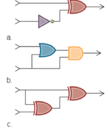
a.
Explanation of Solution
Determine the output of the given circuit.
The stated diagram is shown below,
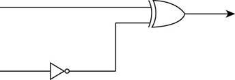
- To find the output of the circuit when the upper input is 1 and the lower input is 0, the diagram contains one XOR gate and inverter, so the Boolean operation of XOR gate and inverter is shown below:
The Boolean XOR operation is shown in table below,
| Input 1 | Input 2 | Output |
| 0 | 0 | 0 |
| 0 | 1 | 1 |
| 1 | 0 | 1 |
| 1 | 1 | 0 |
- First, 0 is the input of inverter which gives the output of inverter and this output of the inverter is the lower input of XOR gate.
The inverter operation is shown in table below,
| Input | output |
| 1 | 0 |
| 0 | 1 |
- The lower input 0 is converted to 1 through inverter gate that means the lower input of XOR gate is 1.
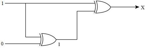
The inputs of XOR gate are shown in Figure below,
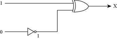
- To represent the output of XOR gate, convert the input of XOR gate through Boolean operation, when both the inputs of XOR gate is 1, then the output of the XOR gate is 0 by Boolean operation XOR table.
Therefore, the required output of the given circuit is “0”.
Determine the output of the given circuit, when the upper input is 0 and the lower input is 1:
- To find the output of the circuit when the upper input is 0 and the lower input is 1, the diagram contains one XOR gate and inverter:
- First, 1 is the input of inverter which gives the output of the inverter and this output of the inverter is the lower input of XOR gate.
- The lower input 1 is converted to 0 through inverter gate, so the lower input of XOR gate is 0.
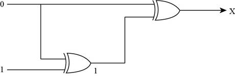
The inputs of XOR gate are shown in Figure below,
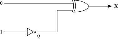
- To represent the output of XOR gate, convert the input of XOR gate through Boolean operation, when both the inputs of XOR gate is 0, then the output of the XOR gate is 1 by Boolean operation XOR table.
Therefore, the required output of the given circuit is “1”.
b.
Explanation of Solution
Determine the output of the given circuit.
The stated diagram is shown below,
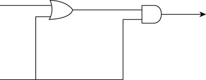
- To find the output of the circuit when the upper input is 1 and the lower input is 0, the diagram contains one OR gate and one AND gate, so the Boolean operation of OR gate and one AND gate is shown below:
The Boolean OR operation is shown in table below,
| Input 1 | Input 2 | output |
| 0 | 0 | 0 |
| 0 | 1 | 1 |
| 1 | 0 | 1 |
| 1 | 1 | 1 |
- First, 1 and 0 are the inputs of OR gate that give the output of the OR gate and this output of OR gate is the upper input of AND gate.
The Boolean AND operation is shown in table below,
| Input 1 | Input 2 | output |
| 0 | 0 | 0 |
| 0 | 1 | 0 |
| 1 | 0 | 0 |
| 1 | 1 | 1 |
The upper input 1 and lower input 0 is converted to 1 through OR gate, so the upper input of AND gate is 1.
The inputs of AND gate are shown in Figure below,
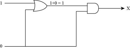
- To represent the output of AND gate, convert the input of AND gate through Boolean operation, when the upper input is 1 and lower input is 0 of AND gate, then the output of the AND gate is 0 by Boolean operation AND table.
Therefore, the required output for the given circuit is “0”.
Determine the output of the given circuit, when the upper input is 0 and the lower input is 1:
- To find the output of the circuit when the upper input is 0 and the lower input is 1, the diagram contains one OR gate and one AND gate:
- First, 0 and 1 is the input of OR gate that gives the output of the OR gate which is the upper input of the AND gate.
The upper input 0 and lower input 1 is converted to 1 through OR gate, so the upper input of AND gate is 1.
The inputs of AND gate are shown in Figure below,
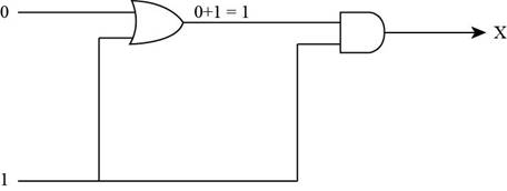
Figure (6)
- To represent the output of AND gate, convert the input of AND gate through Boolean operation, when both the inputs of AND gate is 1 then the output of the AND gate is 1 by Boolean operation AND table.
Therefore, the required output for the given circuit is “1”.
c.
Explanation of Solution
Determine the output of the given circuit:
The stated diagram is shown below,
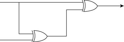
- To find the output of the circuit when the upper input is 1 and the lower input is 0, the diagram contains two XOR gates, so the Boolean operation of XOR gates as shown below:
The Boolean XOR operation is shown in table below,
| Input 1 | Input 2 | output |
| 0 | 0 | 0 |
| 0 | 1 | 1 |
| 1 | 0 | 1 |
| 1 | 1 | 0 |
- First, 1 and 0 are the inputs of XOR gate that give the output of the first XOR gate which is the lower input of second XOR gate.
The upper input 1 and lower input 0 are converted to 1 through XOR gate, so the lower input of second XOR gate is 1.
The inputs of XOR gate are shown in Figure below,
- To represent the output of XOR gate, convert the input of XOR gate through Boolean operation, when both the inputs of XOR gate become 1, then the output of the XOR gate becomes 0 by Boolean operation XOR table.
Therefore, the required output for the given circuit is “0”.
Determine the output of the given circuit, when the upper input is 0 and the lower input is 1:
- To find the output of the circuit when the upper input is 0 and the lower input is 1, the diagram contains two XOR gates:
- First, 0 and 1 are the inputs of first XOR gate that give the output of the first XOR gate which is the lower input of second XOR gate.
The upper input 1 and lower input 0 are converted to 1 through XOR gate, so the lower input of second XOR gate is 1.
The inputs of XOR gate are shown in Figure below,
- To represent the output of XOR gate, convert the input of XOR gate through Boolean operation, when the upper input is 0 and lower input is 1 of XOR gate, then the output of the XOR gate is 1 by Boolean operation XOR table.
Therefore, the required output for the given circuit is “1”.
Want to see more full solutions like this?
Chapter 1 Solutions
Computer Science: An Overview (13th Edition) (What's New in Computer Science)
Additional Engineering Textbook Solutions
SURVEY OF OPERATING SYSTEMS
Introduction To Programming Using Visual Basic (11th Edition)
Modern Database Management
Concepts Of Programming Languages
Electric Circuits. (11th Edition)
Database Concepts (8th Edition)


- Could you help me to know features of the following concepts: - defragmenting. - dynamic disk. - hardware RAIDarrow_forwardwhat is a feature in the Windows Server Security Compliance Toolkit, thank you.arrow_forwardYou will write a program that allows the user to keep track of college locations and details about each location. To begin you will create a College python class that keeps track of the csollege's unique id number, name, address, phone number, maximum students, and average tuition cost. Once you have built the College class, you will write a program that stores College objects in a dictionary while using the College's unique id number as the key. The program should display a menu in this order that lets the user: 1) Add a new College 2) Look up a College 4) Delete an existing College 5) Change an existing College's name, address, phone number, maximum guests, and average tuition cost. 6) Exit the programarrow_forward
- Show all the workarrow_forwardShow all the workarrow_forward[5 marks] Give a recursive definition for the language anb2n where n = 1, 2, 3, ... over the alphabet Ó={a, b}. 2) [12 marks] Consider the following languages over the alphabet ={a ,b}, (i) The language of all words that begin and end an a (ii) The language where every a in a word is immediately followed by at least one b. (a) Express each as a Regular Expression (b) Draw an FA for each language (c) For Language (i), draw a TG using at most 3 states (d) For Language (ii), construct a CFG.arrow_forward
- Question 1 Generate a random sample of standard lognormal data (rlnorm()) for sample size n = 100. Construct histogram estimates of density for this sample using Sturges’ Rule, Scott’s Normal Reference Rule, and the FD Rule. Question 2 Construct a frequency polygon density estimate for the sample in Question 1, using bin width determined by Sturges’ Rule.arrow_forwardGenerate a random sample of standard lognormal data (rlnorm()) for sample size n = 100. Construct histogram estimates of density for this sample using Sturges’ Rule, Scott’s Normal Reference Rule, and the FD Rule.arrow_forwardCan I get help with this case please, thank youarrow_forward
 Systems ArchitectureComputer ScienceISBN:9781305080195Author:Stephen D. BurdPublisher:Cengage Learning
 Programming Logic & Design ComprehensiveComputer ScienceISBN:9781337669405Author:FARRELLPublisher:Cengage
 Operations Research : Applications and AlgorithmsComputer ScienceISBN:9780534380588Author:Wayne L. WinstonPublisher:Brooks Cole
- Np Ms Office 365/Excel 2016 I NtermedComputer ScienceISBN:9781337508841Author:CareyPublisher:Cengage
 EBK JAVA PROGRAMMINGComputer ScienceISBN:9781305480537Author:FARRELLPublisher:CENGAGE LEARNING - CONSIGNMENT
 C++ Programming: From Problem Analysis to Program...Computer ScienceISBN:9781337102087Author:D. S. MalikPublisher:Cengage Learning