
Concept explainers
Videos
Figure Pl.5 shows the topology of a photo-voltaic (PV) system that uses solar cells to supply electrical power to a residence with hybrid electnc vehicle toads (Gurkavnak. 2009). The system consists of a PV array to collect the sun's rays, a battery pack to store energy during the day. a dc/ac inverter to supply ac power to the load, and a bidirectional dc/dc converter to control the terminal voltage of the solar array according to a maxunum power point tracking (MPPT) algorithm. In case of sufficient solar power (solar insolation), the dc/dc converter charges die battery and die solar array supplies power to the load through the dc/ac inverter. Widi less or no solar energy (solar non-insolation). power is supplied from the battery to the load through the dc/dc converter and die dc/ac inverter. Thus, the dc/dc converter must be bidirectional to be able to charge and discharge the batlery. With the MPPT controller providing the reference voltage, the converter operates as a step-up converter (boost) to discharge the battery if the battery is full or a step-down (buck) converter, which charges die batlery if it is not full.7
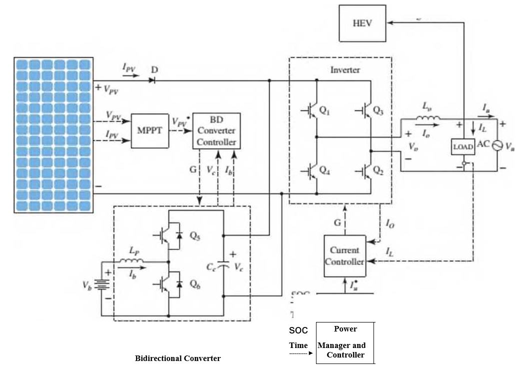
In Figure Pl.5, the Inverter is controlled by die Power Manager and Controller through the Current Controller. The Power Manager and Controller directs the Inverter to take power either from the battery, via the Bidirectional Converter, or the solar array.
of charge (SOC). Draw the follow ing two functional block diagrams for this system:
- A diagram that illustrates the conversion of solar irradiation into energy stored in the battery. In that diagram, the input is the solar irradiance. r(t), and the output is the battery voltage. Vb(t).
- The main diagram, in w hich the input is the desired output voltage. Vr(t) and the output is the actual inverter output voltage, Vo(t) Both of these functional block diagrams should show their major components, including the PV array, MPPT controller, dc/dc converter, battery pack, dc/ac inverter, current controller, and the Power Manager and Controller. Show all signals, including intermediate voltages and currents, time of day. and the SOC of the battery.
Want to see the full answer?
Check out a sample textbook solution
Chapter 1 Solutions
CONTROL SYSTEMS ENGINEERING


- (read image) (answer given)arrow_forward11-5. Compute all the dimensional changes for the steel bar when subjected to the loads shown. The proportional limit of the steel is 230 MPa. 265 kN 100 mm 600 kN 25 mm thickness X Z 600 kN 450 mm E=207×103 MPa; μ= 0.25 265 kNarrow_forwardT₁ F Rd = 0.2 m md = 2 kg T₂ Tz1 Rc = 0.4 m mc = 5 kg m = 3 kgarrow_forward
- 2. Find a basis of solutions by the Frobenius method. Try to identify the series as expansions of known functions. (x + 2)²y" + (x + 2)y' - y = 0 ; Hint: Let: z = x+2arrow_forward1. Find a power series solution in powers of x. y" - y' + x²y = 0arrow_forward3. Find a basis of solutions by the Frobenius method. Try to identify the series as expansions of known functions. 8x2y" +10xy' + (x 1)y = 0 -arrow_forward
- Hello I was going over the solution for this probem and I'm a bit confused on the last part. Can you please explain to me 1^4 was used for the Co of the tubular cross section? Thank you!arrow_forwardBlood (HD = 0.45 in large diameter tubes) is forced through hollow fiber tubes that are 20 µm in diameter.Equating the volumetric flowrate expressions from (1) assuming marginal zone theory and (2) using an apparentviscosity for the blood, estimate the marginal zone thickness at this diameter. The viscosity of plasma is 1.2 cParrow_forwardQ2: Find the shear load on bolt A for the connection shown in Figure 2. Dimensions are in mm Fig. 2 24 0-0 0-0 A 180kN (10 Markarrow_forward
- determine the direction and magnitude of angular velocity ω3 of link CD in the four-bar linkage using the relative velocity graphical methodarrow_forwardFour-bar linkage mechanism, AB=40mm, BC=60mm, CD=70mm, AD=80mm, =60°, w1=10rad/s. Determine the direction and magnitude of w3 using relative motion graphical method. A B 2 3 77777 477777arrow_forwardFour-bar linkage mechanism, AB=40mm, BC=60mm, CD=70mm, AD=80mm, =60°, w1=10rad/s. Determine the direction and magnitude of w3 using relative motion graphical method. A B 2 3 77777 477777arrow_forward
 Principles of Heat Transfer (Activate Learning wi...Mechanical EngineeringISBN:9781305387102Author:Kreith, Frank; Manglik, Raj M.Publisher:Cengage Learning