
Mastering Engineering with Pearson eText -- Standalone Access Card -- for Electrical Engineering: Principles & Applications
7th Edition
ISBN: 9780134486970
Author: Allan R. Hambley
Publisher: PEARSON
expand_more
expand_more
format_list_bulleted
Concept explainers
Videos
Textbook Question
Chapter 1, Problem 1.62P
Consider the circuit shown in Figure P1.62. Find the current
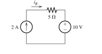
Figure P1.62
Expert Solution & Answer
Want to see the full answer?
Check out a sample textbook solution
Students have asked these similar questions
8
00
!
Required information
Consider the circuit given below.
0/2
points awarded
3 ΚΩ
www
t=0
6kM
Scored
R
1.5i Vc
1 μF
10 V
If R = 5.00 kQ, determine vao+).
The value of va(0) is 1.4545
V.
I want to know what does it look in a breadboard circuit, because I want to created it but I not sure it is build properly, can you give me an illustuation base on this image, it do need to real, something like virutal example
Charge neutrality
Since doped semiconductor remains electroneutral, the concentration
of negative charges equals the concentration of positive charges.
n+ Na,ionized
p+Nd,ionized
np = n;
2
2
N-Na
N N
d
d
р
+
2
2
n =
Nd-Na
2
+
Na
-
2
Na
+n₁
2
71/2
1/2
2
2
+n
Concentration of electrons and holes
1. Calculate concentrations of electrons and holes at room temperature in Si
and Ge with donor concentration of 1.5x10¹7 cm³ and acceptor
concentration of 8x1016 cm-3.
2. Will these concentrations change much with the temperature increase to
100°C?
Chapter 1 Solutions
Mastering Engineering with Pearson eText -- Standalone Access Card -- for Electrical Engineering: Principles & Applications
Ch. 1 - Broadly speaking, what are the two main objectives...Ch. 1 - Prob. 1.2PCh. 1 - List eight subdivisions of electrical engineering.Ch. 1 - Prob. 1.4PCh. 1 - Prob. 1.5PCh. 1 - In the fluid-flow analogy for electrical circuits,...Ch. 1 - The charge of an electron is 1.601019C . A current...Ch. 1 - The ends of a length of wire are labeled a and b....Ch. 1 - The circuit element shown in Figure P1.9 has v=12V...Ch. 1 - Prob. 1.10P
Ch. 1 - The net charge through a cross section of a...Ch. 1 - The current through a particular circuit element...Ch. 1 - The current through a given circuit element is...Ch. 1 - The net charge through a cross section of a...Ch. 1 - A copper wire has a diameter of 2.05 mm and...Ch. 1 - A certain lead acid storage battery has a mass of...Ch. 1 - A circuit element having terminals a and b has...Ch. 1 - An electron moves through a voltage of 9 V from...Ch. 1 - A typical “deep-cycle” battery (used for electric...Ch. 1 - Define the term passive reference configuration....Ch. 1 - Compute the power for each element shown in Figure...Ch. 1 - The terminals of an electrical device are labeled...Ch. 1 - The terminals of a certain battery are labeled a...Ch. 1 - The element shown in Figure P1.24 I has v(t)=10V...Ch. 1 - The current and voltage of an electrical device...Ch. 1 - Suppose that the cost of electrical energy is...Ch. 1 - Figure P1.27 shows an ammeter (AM) and voltmeter...Ch. 1 - Repeat Problem P1.27 with the meters connected as...Ch. 1 - A certain type of D-cell battery that costs $0.50...Ch. 1 - The electronics aboard a certain sailboat consume...Ch. 1 - What s a node in an electrical circuit? Identify...Ch. 1 - State Kirchhoff’s current law.Ch. 1 - Two electrical elements are connected in series....Ch. 1 - Suppose that in the fluid-flow analogy for an...Ch. 1 - Identify elements that are in series in the...Ch. 1 - Consider the circuit shown in Figure P1.36. Which...Ch. 1 - Use KCL to find the values of ia, ic , and id for...Ch. 1 - Find the values of the other currents in Figure...Ch. 1 - Prob. 1.39PCh. 1 - State Kirchhoff’s voltage law.Ch. 1 - Consider the circuit shown in Figure P1.36. Which...Ch. 1 - Use KVL to solve for the voltages va , vb, and vc...Ch. 1 - Solve for the other voltages shown in Figure P1.43...Ch. 1 - Use KVL and KCL to solve for the labeled currents...Ch. 1 - Identify elements that are in parallel in Figure...Ch. 1 - Points a, b, c, and d appear in a certain circuit....Ch. 1 - In your own words, define an ideal conductor; an...Ch. 1 - Name four types of dependent sources and give the...Ch. 1 - State Ohm’s law, including references.Ch. 1 - Draw a circuit that contains a 5 resistance, a...Ch. 1 - Repeat Problem P1.50, placing all three elements...Ch. 1 - The resistance of a certain copper wire is 0.5. ....Ch. 1 - Draw a circuit that contains a 5 resistor, a 10-V...Ch. 1 - Draw a circuit that contains a 5 resistor, a 10-V...Ch. 1 - A power of 100 W is delivered to a certain...Ch. 1 - The voltage across a 10 resistor is given by...Ch. 1 - The voltage across a 10 resistor is given by...Ch. 1 - A certain wire has a resistance of 0.5 . Find the...Ch. 1 - Plot i versus v to scale for each of the parts of...Ch. 1 - Which of the following are self-contradictory...Ch. 1 - Consider the circuit shown in Figure P1.61. Find...Ch. 1 - Consider the circuit shown in Figure P1.62. Find...Ch. 1 - Consider the circuit shown in Figure P1.63. Find...Ch. 1 - Consider the circuit shown in Figure P1.64. Use...Ch. 1 - Determine the value of Ix in the circuit shown in...Ch. 1 - Consider the circuit shown in Figure P1.66. Figure...Ch. 1 - Prob. 1.67PCh. 1 - Consider the circuit shown in Figure P1.68. Figure...Ch. 1 - Solve for the currents shown in Figure P1.69....Ch. 1 - The circuit shown in Figure P1.70 contains a...Ch. 1 - Determine the value of vx and iy in the circuit...Ch. 1 - A 10-V independent voltage source is in series...Ch. 1 - A 10-V independent voltage source is in parallel...Ch. 1 - Consider the circuit shown in Figure P1.74. Figure...Ch. 1 - The circuit shown in Figure P1.75 contains a...Ch. 1 - For the circuit shown in Figure P1.76, solve for...Ch. 1 - For the circuit shown in Figure P1.77, solve for...Ch. 1 - Match each entry in Table T1.1(a) with the best...Ch. 1 - Prob. 1.2PTCh. 1 - The circuit of Figure T1.3 has I1=3A , I2=1A ,...Ch. 1 - The circuit shown in Figure T1.4 has Vs=12V ,...Ch. 1 - We are given Vs=15V , R=10 , and =0.3S for the...Ch. 1 - We are given i4=2A for the circuit of Figure T1.6....
Additional Engineering Textbook Solutions
Find more solutions based on key concepts
What is an uninitialized variable?
Starting Out with Programming Logic and Design (5th Edition) (What's New in Computer Science)
What are the design issues for character string types?
Concepts Of Programming Languages
Assume a telephone signal travels through a cable at two-thirds the speed of light. How long does it take the s...
Electric Circuits. (11th Edition)
17–1C A high-speed aircraft is cruising in still air. How does the temperature of air at the nose of the aircra...
Thermodynamics: An Engineering Approach
Write a summary list of the problem-solving steps identified in the chapter, using your own words.
BASIC BIOMECHANICS
How are relationships between tables expressed in a relational database?
Modern Database Management
Knowledge Booster


Learn more about
Need a deep-dive on the concept behind this application? Look no further. Learn more about this topic, electrical-engineering and related others by exploring similar questions and additional content below.Similar questions
- Answer the questions on the end of the image pleasearrow_forwardAnswer these two questions on the end of the image, please 1.Calculate intrinsic carrier concentration for Si, Ge and GaAs at temperatures -20°C, 20°C (room temperature) and 120°C 2.Compare the obtained data with n and p shown on previous slide 25arrow_forwardCan you help me achieve the requirements using Arduino? I have encountered some issues with these requirements. Q.2: Suppose you have two push buttons connected to ports (0 & 1) and four LED's connected to ports (6-9). Write a program to flash ON the odd LED's if we press the switch 0 for 4s, flash ON the even LED's if we press the switch 1 for 5s and flash ON all the LED's otherwise for 6s.arrow_forward
- Charge carrier concentration in doped semiconductor: compensation n = Na - Na Na - Na >> ni n-type p = n₁²/n 2 if N₂ >> N₁, n = N₁_ and _p=n² / Na d p = Na-Nd p-type Na-Na >> n₁ d 2 n = n₁₂²/p 2 if N₁ >> N₁, p = N₁ and n = n² / Na a n-type Dopant compensation: Examples d n = Na-N₁ = 4×10¹ cm¯ -3 ++++++ n = 4×1016 cm-³ N=6×1016 cm-3 p=n/n=1020/4×1016 = 2.5×10³ cm p-type -3 p=Na-N₁ =8×10 −6×1016 = 2×10¹6 cm³ n=n²/p=1020/2×101 =5×10³ cm³ N2×1016 cm³ ++++++ N=6x1016 cm-3 N = 8×1016 cm-3 p=2×1016 cm³ The resulting charge carrier concentration in compensated semiconductor approximately equals the difference between the donor and acceptor concentrations. Charge carrier concentration in n-type and p-type semiconductors 1. Calculate concentrations of electrons and holes at room temperature in Si containing 2x1017 cm³ of donors and 8x10¹⁶ -3 cm³ of acceptors. Assume that Na, Nd >> n;. αν 2. Calculate concentrations of electrons and holes at room temperature in Ge containing 2x10¹7 cm³ of…arrow_forwardlonization energy of dopants in semiconductors lonization energy of shallow donors and acceptors can be evaluated using hydrogenic model: lonization energy E Hion and orbital radius a, of hydrogen atom Hydrogen Atom moe4 EHion = 13.6 eV a = 8ε²h² Απερη mee² = 5.2918 x 10⁻¹¹ m lonization energy Eion and orbital radius D,A of donors and acceptors electron m* e4 Eion = ~50 meV 8K² &²h² 4πεερη2 "D,A 1 nm m*e² Orbit of an electron bound to a donor in a semiconductor crystal. Energy levels of donors and acceptors Conduction Band ↓ Ec -Ed Donor Level Donor ionization energy Acceptor ionization energy Acceptor Level Εα Ev Valence Band Ionization energy of selected donors and acceptors in silicon Donors Acceptors Dopant Sb P As B Al In Ionization energy, Ec-Ed or Ea-E, (meV) 39 44 54 45 57 160 Hydrogenic model of donors and acceptors Calculate the ionization energies and orbit radii of donors and acceptors in Si and Ge. Dielectric constant of silicon is k = 11.7. Dielectric constant of…arrow_forwardI need help in construct a method in matlab to find the voltage of VR1 to VR4, rhe current, and the power base on that circuit Nominal or Theortical: E1 = 3V , E2 = 9V, E3 = 1.5V R1 =10Kohm, R2 =2Kohm, R3 =1Kohm, R4 =16Kohmarrow_forward
- Procedure:- 1- Connect the cct. shown in fig.(2). a ADDs Ds Fig.(2) 2-For resistive load, measure le output voltage by using oscilloscope; then sketch this wave. 3- Measure the average values f VL and IL: 4- Repeat steps 2 & 3 but for RL load. Report:- 1- Calculate the D.C. output vcl age theoretically and compare it with the test value. 2- Calculate the harmonic cont :nts of the load voltage, and explain how filter components may be selected. 3- Compare between the three-phase half & full-wave uncontrolled bridge rectifier. 4- Draw the waveform for the c:t. shown in fig.(2) but after replaced Di and D3 by thyristors with a = 30° and a2 = 90° 5- Draw the waveform for the cct. shown in fig.(2) but after replace the 6-diodes by 6- thyristor. 6- Discuss your results. Draw the waves on graph paper please Please solve No. 4 and 5arrow_forwardnot use ai please chat gpt How to draw this in LtSpicearrow_forward4. Discussion: Compare between theoretical effect of KI at first order and second order systems regarding steady-state errors and transient responses with the practical In Experiment Integral Controllerarrow_forward
- I would appreciate your help in solving the questions and drawing.arrow_forward498 FET AMPLIFIERS AND SWITCHING CIRCUITS FIGURE 9-54 FIGURE 0.55 5. Identify the type of FET and its bias arrangement in Figure 9-54. Ideally, what is Vas? 6. Calculate the dc voltages from each terminal to ground for the FETs in Figure 9-54. +15 V -10 V +12 V 8 mA Ro 3 mA 1.0 ΚΩ Rp 1.5 ΚΩ Rp 6 mA R₁ 1.0 ΚΩ 10 ΚΩ RG * 10 ΜΩ RG 10 ΜΩ ww Rs R₂ • 330 Ω · 4.7 ΚΩ (a) (b) 7. Identify each characteristic curve in Figure 9-55 by the type of FET that it represents.arrow_forwardCan you help me achieve the requirements using Arduino? I have encountered some issues with these requirements. 1. Functionality:** The system must control 3 LEDS (Red, Green, and Blue) to produce at least 4 different lighting modes: a. **Mode 1: All LEDs blink simultaneously at 1-second intervals. b. Mode 2: LEDs blink in sequence (Red → Green → Blue) with a 500ms delay between each LED. c. **Mode 3:** LEDs fade in and out smoothly (PWM control) in the order Red Green → Blue. d. **Mode 4: Custom mode (e.g., random blinking or a pattern of your choice). 2. Constraints:** -Use only one push button to cycle through the modes. -The system must operate within a 5V power supply. -The total current drawn by the LEDs must not exceed 100mA. -Use resistors to limit the current through each LED appropriately. 3. Design Process:** -Analysis: Calculate the required resistor values for each LED to ensure they operate within their specified current limits. Synthesis: Develop a circuit schematic and…arrow_forward
arrow_back_ios
SEE MORE QUESTIONS
arrow_forward_ios
Recommended textbooks for you
 Introductory Circuit Analysis (13th Edition)Electrical EngineeringISBN:9780133923605Author:Robert L. BoylestadPublisher:PEARSON
 Delmar's Standard Textbook Of ElectricityElectrical EngineeringISBN:9781337900348Author:Stephen L. HermanPublisher:Cengage Learning
 Programmable Logic ControllersElectrical EngineeringISBN:9780073373843Author:Frank D. PetruzellaPublisher:McGraw-Hill Education
 Fundamentals of Electric CircuitsElectrical EngineeringISBN:9780078028229Author:Charles K Alexander, Matthew SadikuPublisher:McGraw-Hill Education
 Electric Circuits. (11th Edition)Electrical EngineeringISBN:9780134746968Author:James W. Nilsson, Susan RiedelPublisher:PEARSON
 Engineering ElectromagneticsElectrical EngineeringISBN:9780078028151Author:Hayt, William H. (william Hart), Jr, BUCK, John A.Publisher:Mcgraw-hill Education,
Introductory Circuit Analysis (13th Edition)
Electrical Engineering
ISBN:9780133923605
Author:Robert L. Boylestad
Publisher:PEARSON
Delmar's Standard Textbook Of Electricity
Electrical Engineering
ISBN:9781337900348
Author:Stephen L. Herman
Publisher:Cengage Learning
Programmable Logic Controllers
Electrical Engineering
ISBN:9780073373843
Author:Frank D. Petruzella
Publisher:McGraw-Hill Education
Fundamentals of Electric Circuits
Electrical Engineering
ISBN:9780078028229
Author:Charles K Alexander, Matthew Sadiku
Publisher:McGraw-Hill Education
Electric Circuits. (11th Edition)
Electrical Engineering
ISBN:9780134746968
Author:James W. Nilsson, Susan Riedel
Publisher:PEARSON
Engineering Electromagnetics
Electrical Engineering
ISBN:9780078028151
Author:Hayt, William H. (william Hart), Jr, BUCK, John A.
Publisher:Mcgraw-hill Education,
Conductivity and Semiconductors; Author: Professor Dave Explains;https://www.youtube.com/watch?v=5zz6LlDVRl0;License: Standard Youtube License