
Concept explainers
Videos
Figure P1.27 shows an ammeter (AM) and voltmeter (VM) connected to measure the current and voltage, respectively, for circuit element A.When current actually enters the + terminal of the ammeter, the reading is positive, and when current leaves the + terminal, the reading is negative. If the actual voltage polarity is positive at the + terminal of the VM, the reading is positive; otherwise, it is negative. (Actually, for the connection shown, the ammeter reads the sum of the current in element A and the very small current taken by the voltmeter. For purposes of this problem, assume that the current taken by the voltmeter is negligible.) Find the power for element A and state whether energy is being delivered to element A or taken from it if
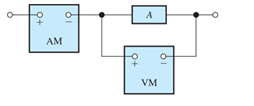
Figure P1.27
- the ammeter reading is +2 A and the voltmeter reading is +30 V;
Want to see the full answer?
Check out a sample textbook solution
Chapter 1 Solutions
Pearson eText for Electrical Engineering: Principles & Applications -- Instant Access (Pearson+)
Additional Engineering Textbook Solutions
Thinking Like an Engineer: An Active Learning Approach (4th Edition)
Mechanics of Materials (10th Edition)
Vector Mechanics for Engineers: Statics
SURVEY OF OPERATING SYSTEMS
Vector Mechanics for Engineers: Statics and Dynamics
Database Concepts (8th Edition)


- Don't use ai to answer I will report you answerarrow_forwardDon't use ai to answer I will report you answerarrow_forwardtype (o) bT S+αT Profational controller a = b = 5, T-La |kp| 50 5+50 kp=20,50,70 ② type (1) bT 5(stat) a=b=5,T= 1 ✓ KT 5 SC5+5 kp=20, 50, 70 (Find Wny, ess for type (a) and (1))arrow_forward
- 2. Write an expression of the two sinusoidal voltage waveforms whose effective value is 7.071 V and whose phase difference is 90 degrees. Draw the phasor of those two sinusoidal waveforms in the complex plane.arrow_forward2. Determine developed torque and shaft torque of 220-V, 4-pole series motor with 800 conductors wave-connected supplying a load of 8.2kW by taking 45A from the mains. The flux per pole is 25 mWb and its armature circuit resistance is 0.60. Ans.[143.25 Nm, 135.25 Nm]arrow_forward7. resistance): The practical capacitor can be simplified as the model below (ESR: equivalent series 10 μF ESR W From a datasheet, it is known that a 10 µF aluminum electrolytic capacitor has an impedance of 2800 mOhm at the 100 kHz testing condition. (1) Calculate the ESR under the above testing condition; (2) Calculate the phase shift between the voltage and current at 100 Hz and 10k Hz sinusoidal excitation conditions.arrow_forward
- 5. A circuit has the following AC sources: y₁ = 5 cos(wt + 30°), y₂ = 4 cos(2wt + 120°), y3 = 3 cos(4wt - 60°), y4 = 6 cos(2wt - 120°), y = 2√2cos(wt - 60°): (1) Identify fundamental sources and harmonics. (2) Using phasor approach to simplify y₁ + y2 y3 y4 y5 as much as possible.arrow_forward6. A practical 10 μH wire wounded inductor has a series parasitic resistance of 0.4 Ohm, as shown in the figure below. a 10 pH 0.4 Ω W° b If an AC current y₁ = 4cos (20πt + 60°) is supplied to this inductor, (1) calculate the voltage across the inductor terminals a and b. (2) express the inductor terminal voltage and current in the complex plane. (3) calculate the phase shift between inductor terminal voltage and current If an AC current y₂ = 4cos (2000лt + 60°) is supplied to this inductor, (4) calculate the voltage across the inductor terminals a and b. (5) express the inductor terminal voltage and current in the complex plane. (6) calculate the phase shift between inductor terminal voltage and currentarrow_forward1. As shown below, an LED lightbulb is connected to the grid power. The LED lightbulb has a rated power of 15 W, and the gird voltage is 120 V 60 Hz. Based on the above information (1) what is the peak value and effective value of the current flowing through the LED light bulb, (2) write an expression of the current flowing through the LED light bulb.arrow_forward
 Introductory Circuit Analysis (13th Edition)Electrical EngineeringISBN:9780133923605Author:Robert L. BoylestadPublisher:PEARSON
 Delmar's Standard Textbook Of ElectricityElectrical EngineeringISBN:9781337900348Author:Stephen L. HermanPublisher:Cengage Learning
 Programmable Logic ControllersElectrical EngineeringISBN:9780073373843Author:Frank D. PetruzellaPublisher:McGraw-Hill Education
 Fundamentals of Electric CircuitsElectrical EngineeringISBN:9780078028229Author:Charles K Alexander, Matthew SadikuPublisher:McGraw-Hill Education
 Electric Circuits. (11th Edition)Electrical EngineeringISBN:9780134746968Author:James W. Nilsson, Susan RiedelPublisher:PEARSON
 Engineering ElectromagneticsElectrical EngineeringISBN:9780078028151Author:Hayt, William H. (william Hart), Jr, BUCK, John A.Publisher:Mcgraw-hill Education,