EBK THE ANALYSIS AND DESIGN OF LINEAR C
8th Edition
ISBN: 9781119140320
Author: Toussaint
Publisher: VST
expand_more
expand_more
format_list_bulleted
Textbook Question
Chapter 1, Problem 1.24P
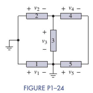
In Figure P1-24 the voltage

Expert Solution & Answer
Want to see the full answer?
Check out a sample textbook solution
Students have asked these similar questions
A left-sided signal x(t)=-ebt u(-t):
A right-sided signal x(t)=e¯at u(t)
Find Laplace transform of x(t)=u(t)
Find Laplace transform of x(t) = −e¯btu(−t) + e¯atu(t)
Find Laplace transform of x(t) = u(t)
Expert only, don't use artificial intelligence ,or screenshot of an AI solving steps
Chapter 1 Solutions
EBK THE ANALYSIS AND DESIGN OF LINEAR C
Ch. 1 - Given an electrical quantity described in terms of...Ch. 1 - Express the following quantities to the nearest...Ch. 1 - An ampere-hour (Ah) meter measures the time...Ch. 1 - Electric power companies measure energy...Ch. 1 - Fill in the blanks in the following statements. To...Ch. 1 - Which of the two entries is larger? 1000...Ch. 1 - A wire carries a constant current of 30A. How many...Ch. 1 - The net positive charge flowing through a device...Ch. 1 - Figure P1-9 shows a plot of the net positive...Ch. 1 - The net negative charge flowing through a device...
Ch. 1 - A cell phone charger outputs 9.6 V and is...Ch. 1 - For 0t5s, the current through a device is...Ch. 1 - The charge flowing through a device is...Ch. 1 - The 12-V automobile battery in Figure P1-14 has an...Ch. 1 - The current through a device is zero for t0 and is...Ch. 1 - A string of holiday lights is protected by a 12A...Ch. 1 - When illuminated the relationship for a photocell...Ch. 1 - A new 6-V alkaline lantern battery delivers...Ch. 1 - The maximum current allowed by a device's power...Ch. 1 - Traffic lights are being converted from...Ch. 1 - Two electrical devices are connected as shown in...Ch. 1 - Figure P1-22 shows an electric circuit with a...Ch. 1 - Figure P1-22 shows an electric circuit with a...Ch. 1 - In Figure P1-24 the voltage v2 is 10 V and v4 is 5...Ch. 1 - For t0, the voltage across and power absorbed by a...Ch. 1 - Repeat Problem 1-22 using MATLAB to perform the...Ch. 1 - Using the passive sign convention, the voltage...Ch. 1 - Power Ratio (PR) in dB A stereo amplifier takes...Ch. 1 - AC to DC Converter A manufacturer's data sheet for...Ch. 1 - Charge-Storage Device A capacitor is a...Ch. 1 - Compute Data Sheet A manufacturer's data sheet for...Ch. 1 - Light Source Comparison A Today people have three...
Additional Engineering Textbook Solutions
Find more solutions based on key concepts
The switch shown in Fig. P 7.4 has been open for a long time before closing at t = 0.
Figure P7.4
Find io(0−),...
Electric Circuits. (11th Edition)
What will the following code display? int funny = 7, serious = 15; funny = serious 2; switch (funny) { case 0 ...
Starting Out with Java: From Control Structures through Objects (7th Edition) (What's New in Computer Science)
Sales Tax Program Refactoring Programming Exercise #6 in Chapter 2 was the Sales Tax program. For that exercise...
Starting Out with Python (4th Edition)
In Exercises 49 through 54, find the value of the given function. Math.Round(2.6)
Introduction To Programming Using Visual Basic (11th Edition)
Write statements that can be used in a Java program to read two integers and display the number of integers tha...
Java: An Introduction to Problem Solving and Programming (8th Edition)
ICA 8-52
The heat transfer coefficient of steel is 25 watts per square meter degree Celsius [W/(m2 °C)]. Conver...
Thinking Like an Engineer: An Active Learning Approach (4th Edition)
Knowledge Booster
Learn more about
Need a deep-dive on the concept behind this application? Look no further. Learn more about this topic, electrical-engineering and related others by exploring similar questions and additional content below.Similar questions
- find inverse LT for the following functions 1- [0.2s+1.4] s2+1.96. 2. L-1 5s+1 Ls2-25. 4s+32 3. L- L(s2-16).arrow_forwardQ Figurel shows the creation of the Frequency Reuse Pattern Using the Cluster Size K (A) illustrates how i and j can be used to locate a co-channel cell. Juster Cluster CB Cluster 2 X=7(i=2,j=1)arrow_forwardDon't use ai to answer I will report you answerarrow_forward
- Q2. For the transformer shown in Fig. 1. A. Plot the winding connection for the transformer and justify your answer. (4M) B. If the transformer is adopted in 12 pulse diode rectifier, where two-series connected bridge rectifiers are used to supply a highly inductive load with 100 A. (i) Select a suitable turns ratio for the transformer (ii) Plot the line current of each winding ( secondary + primary) showing the current magnitude at each interval (iii) Use Fourier Page 1 of 3 analysis to obtain the Fourier series of all line currents then calculate the THD of the input current. (8=0° (16M) (Y) = 30° Fig. 1 P. I v Iarrow_forwardQ2. For the transformer shown in Fig.1, A. Find the phase shift between the primary and star-connected secondary. B. If the transformer is adopted in a 12-pulse diode rectifier, where a two-series connected bridge rectifier is connected in series and supplies a highly inductive load (i) Select a suitable turns ratio for the transformer (ii) Plot the line current of each winding (secondary + primary). (iii)Using Fourier analysis to obtain the Fourier series of all line currents, then calculate the THD of the input current. (iv) Draw the output voltage of the first and second rectifiers and give the relation of the total output voltage. N2 B C Fig. 1 N3 aarrow_forwardQ2.A. It is planned to use the transformer shown in Fig. 1, a 12-pulse rectifier. Each secondary is connected to three phase controlled bridge rectifier. The two rectifiers are connected in series to supply a highly inductive load. 1. Based on the phasor relationship between different windings. If suitable turns ratio is selected, is it possible to use this transformer to produce 12 pulse output voltage? Show the reason behind your answer. 2. Assuming this arrangement is possible to be used in 12-pulse rectifier, draw the output voltage of the 1st and 2nd rectifier and give the relation of the total output voltage. 3. Use the Fourier analysis to show the harmonics in all line currents of the transformer. A B in C Fig. 1 b la a 2 b.arrow_forward
arrow_back_ios
SEE MORE QUESTIONS
arrow_forward_ios
Recommended textbooks for you
 Delmar's Standard Textbook Of ElectricityElectrical EngineeringISBN:9781337900348Author:Stephen L. HermanPublisher:Cengage Learning

Delmar's Standard Textbook Of Electricity
Electrical Engineering
ISBN:9781337900348
Author:Stephen L. Herman
Publisher:Cengage Learning
Lesson 2 - Source Transformations, Part 2 (Engineering Circuits); Author: Math and Science;https://www.youtube.com/watch?v=7gno74RhVGQ;License: Standard Youtube License