x₂ (t) AS (a) K₁ = 2, K₂ = 11 (b) K₁ = 2, K₂ = 9 (c) K₁ = 9, K₂ = 2 (d) K₁ = 11, K₂ = 2 -K₂ Find values of K, and K₂ to yield poles at s = -1 ±j3. x, (t) When K₁ = 6 and K₂ = 9, find the poles of the system. (a) S₁ = -3, S₂ = -3 (b) s₁ = -3+j3, S₂ = -3-j3 (c) s₁ = -3+j, $₂ = -3-j (d) $₁ = -2, S₂ = -4
x₂ (t) AS (a) K₁ = 2, K₂ = 11 (b) K₁ = 2, K₂ = 9 (c) K₁ = 9, K₂ = 2 (d) K₁ = 11, K₂ = 2 -K₂ Find values of K, and K₂ to yield poles at s = -1 ±j3. x, (t) When K₁ = 6 and K₂ = 9, find the poles of the system. (a) S₁ = -3, S₂ = -3 (b) s₁ = -3+j3, S₂ = -3-j3 (c) s₁ = -3+j, $₂ = -3-j (d) $₁ = -2, S₂ = -4

Power System Analysis and Design (MindTap Course List)
6th Edition
ISBN:9781305632134
Author:J. Duncan Glover, Thomas Overbye, Mulukutla S. Sarma
Publisher:J. Duncan Glover, Thomas Overbye, Mulukutla S. Sarma
Chapter6: Power Flows
Section: Chapter Questions
Problem 6.4P

Related questions
Question

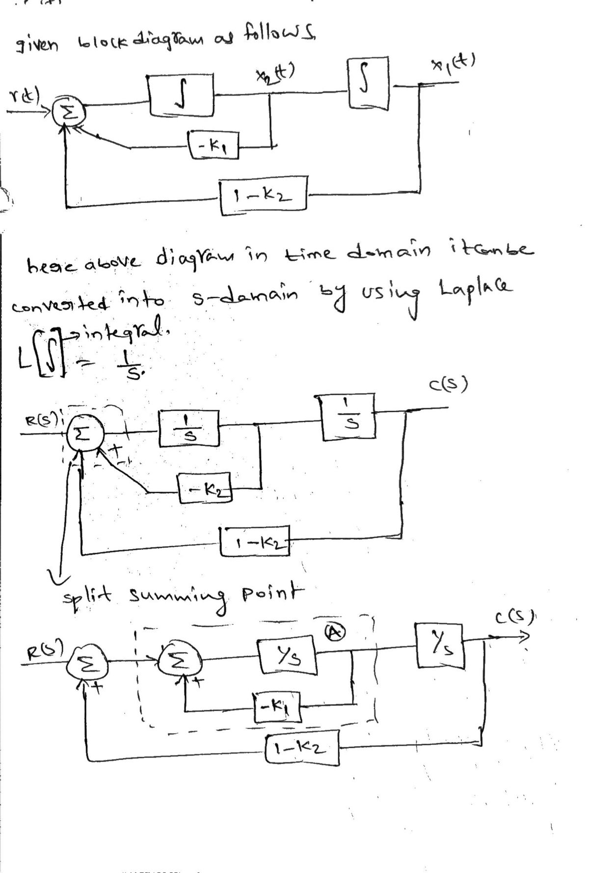
Transcribed Image Text:### Control Systems Problem
**Objective:** Find values of \( K_1 \) and \( K_2 \) to yield poles at \( s = -1 \pm j 3 \).
**Options:**
- (a) \( K_1 = 2, K_2 = 11 \)
- (b) \( K_1 = 2, K_2 = 9 \)
- (c) \( K_1 = 9, K_2 = 2 \)
- (d) \( K_1 = 1, K_2 = 2 \)
**Question:** When \( K_1 = 6 \) and \( K_2 = 9 \), find the poles of the system.
**Calculated Poles:**
- (a) \( s_1 = -3, s_2 = -3 \)
- (b) \( s_1 = -4, s_2 = -3\)
- (c) \( s_1 = -3 + j 3, s_2 = -3 - j 3 \)
- (d) \( s_1 = 2.5, s_2 = 4 \)
**Diagram Analysis:**
The block diagram represents a control system. The components include:
1. **Integrator (\(\int\)):** Symbolized by a block with an integration sign, indicating the integration of the input signal.
2. **Negative Feedback (-K1):** A block representing a multiplication with the constant \(-K_1\).
3. **Additional Feedback (1-K2):** A block indicating the system output is multiplied by \(1-K_2\) before feeding back to the system input.
4. **Summing Junction:** Located at the circuit junctions with typical plus and minus signs indicating the addition and subtraction of signals.
5. **Signal Path:** The lines connecting each block highlight the flow of control signals through the system.
The goal is to manipulate the values \( K_1 \) and \( K_2 \) such that the system provides a desired response characterized by specific pole placements.
Expert Solution
Step 1

Step by step
Solved in 3 steps with 3 images

Knowledge Booster


Learn more about
Need a deep-dive on the concept behind this application? Look no further. Learn more about this topic, electrical-engineering and related others by exploring similar questions and additional content below.Recommended textbooks for you
Power System Analysis and Design (MindTap Course …
Electrical Engineering
ISBN:
9781305632134
Author:
J. Duncan Glover, Thomas Overbye, Mulukutla S. Sarma
Publisher:
Cengage Learning
Power System Analysis and Design (MindTap Course …
Electrical Engineering
ISBN:
9781305632134
Author:
J. Duncan Glover, Thomas Overbye, Mulukutla S. Sarma
Publisher:
Cengage Learning