Vo Answer: Answer: R 2R Answer: 3R ww a R 3R Consider the network above, with Io =2A. Vo=220V. and R = 39. a. First. a 480 resistor is connected between nodes a and b. What is the current through this resistor (arrow is down)? Answer: bo 4R ww b. Next. a 4A source is connected between nodes a and b. with the current arrow pointing from b to a. What is the voltage across this source (+ at a)? 2R Io c. Finally, what value of a load resistance connected between a and b will dissipate the largest amount of power? d. What is the maximum possible power dissipated by the load resistance?
Vo Answer: Answer: R 2R Answer: 3R ww a R 3R Consider the network above, with Io =2A. Vo=220V. and R = 39. a. First. a 480 resistor is connected between nodes a and b. What is the current through this resistor (arrow is down)? Answer: bo 4R ww b. Next. a 4A source is connected between nodes a and b. with the current arrow pointing from b to a. What is the voltage across this source (+ at a)? 2R Io c. Finally, what value of a load resistance connected between a and b will dissipate the largest amount of power? d. What is the maximum possible power dissipated by the load resistance?

Introductory Circuit Analysis (13th Edition)
13th Edition
ISBN:9780133923605
Author:Robert L. Boylestad
Publisher:Robert L. Boylestad
Chapter1: Introduction
Section: Chapter Questions
Problem 1P: Visit your local library (at school or home) and describe the extent to which it provides literature...

Related questions

Concept explainers
KVL and KCL
KVL stands for Kirchhoff voltage law. KVL states that the total voltage drops around the loop in any closed electric circuit is equal to the sum of total voltage drop in the same closed loop.
Sign Convention
Science and technology incorporate some ideas and techniques of their own to understand a system skilfully and easily. These techniques are called conventions. For example: Sign conventions of mirrors are used to understand the phenomenon of reflection and refraction in an easier way.
Question

Transcribed Image Text:### Circuit Analysis Exercise
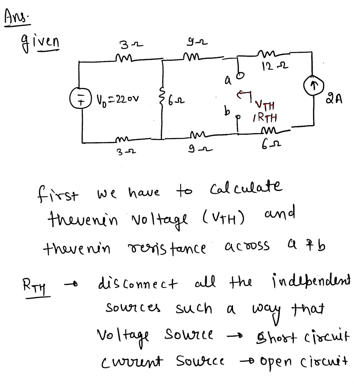
Consider the electrical network diagram above where:
- \( I_0 = 2A \)
- \( V_0 = 220V \)
- \( R = 3\Omega \)
The circuit includes the following components:
- A voltage source \( V_0 \) connected in series with two resistors \( R \).
- Three branches: one with \( 3R \), another with a combination of \( 3R \) and \( 4R \) in series, and a branch with two resistors \( 2R \) and a constant current source \( I_0 \).
This is presented in a mesh configuration with points labeled \( a \) and \( b \) for potential connections or modifications to the circuit.
#### Questions:
**a.** A 4Ω resistor is inserted between nodes \( a \) and \( b \). What is the current through this resistor (given that the arrow is downwards)?
**Answer: __________**
**b.** Next, a 4A current source is connected between nodes \( a \) and \( b \), with the current arrow pointing from \( b \) to \( a \). What is the voltage across this source with \( + \) at \( a \)?
**Answer: __________**
**c.** Determine the value of load resistance connected between \( a \) and \( b \) for maximal power dissipation.
**Answer: __________**
**d.** Calculate the maximum possible power dissipated by the load resistance.
**Answer: __________**
### Explanation of Diagram
- **Voltage Source (\( V_0 \)):** A direct current voltage source set at 220V provides power to the circuit.
- **Resistors (\( R, 2R, 3R, 4R \)):** The circuit includes resistors of different magnitudes to provide resistance against the current flow, following the color-coded lines.
- **Current Source (\( I_0 \)):** A constant current source with 2A located in the bottom mesh provides a constant current independently of the voltage.
Analyze the circuit based on these conditions and solve each part systematically by applying circuit laws such as Ohm’s Law and the principles of series and parallel circuits.
Expert Solution
Step 1

Step by step
Solved in 3 steps with 3 images

Knowledge Booster


Learn more about
Need a deep-dive on the concept behind this application? Look no further. Learn more about this topic, electrical-engineering and related others by exploring similar questions and additional content below.Recommended textbooks for you
Introductory Circuit Analysis (13th Edition)
Electrical Engineering
ISBN:
9780133923605
Author:
Robert L. Boylestad
Publisher:
PEARSON

Delmar's Standard Textbook Of Electricity
Electrical Engineering
ISBN:
9781337900348
Author:
Stephen L. Herman
Publisher:
Cengage Learning

Programmable Logic Controllers
Electrical Engineering
ISBN:
9780073373843
Author:
Frank D. Petruzella
Publisher:
McGraw-Hill Education
Introductory Circuit Analysis (13th Edition)
Electrical Engineering
ISBN:
9780133923605
Author:
Robert L. Boylestad
Publisher:
PEARSON
Delmar's Standard Textbook Of Electricity
Electrical Engineering
ISBN:
9781337900348
Author:
Stephen L. Herman
Publisher:
Cengage Learning
Programmable Logic Controllers
Electrical Engineering
ISBN:
9780073373843
Author:
Frank D. Petruzella
Publisher:
McGraw-Hill Education

Fundamentals of Electric Circuits
Electrical Engineering
ISBN:
9780078028229
Author:
Charles K Alexander, Matthew Sadiku
Publisher:
McGraw-Hill Education

Electric Circuits. (11th Edition)
Electrical Engineering
ISBN:
9780134746968
Author:
James W. Nilsson, Susan Riedel
Publisher:
PEARSON

Engineering Electromagnetics
Electrical Engineering
ISBN:
9780078028151
Author:
Hayt, William H. (william Hart), Jr, BUCK, John A.
Publisher:
Mcgraw-hill Education,