A R₁₂ R4 B 5V (+ 10 V ỗ +- R5 R₂ с Ro R3 D

Introductory Circuit Analysis (13th Edition)
13th Edition
ISBN:9780133923605
Author:Robert L. Boylestad
Publisher:Robert L. Boylestad
Chapter1: Introduction
Section: Chapter Questions
Problem 1P: Visit your local library (at school or home) and describe the extent to which it provides literature...

Related questions
Question
In the electrical circuit, calculate the mesh currents in each loop.

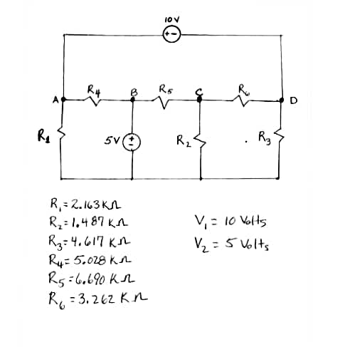
Transcribed Image Text:**Electrical Circuit Analysis**
This image presents a schematic of an electrical circuit with multiple resistors and voltage sources. Below is a detailed breakdown of the circuit and its components based on the provided information.
**Circuit Diagram Description:**
- **Voltage Sources:**
- There is a 10V voltage source at the top of the circuit.
- A 5V voltage source is located between nodes A and B.
- **Resistors:**
- \( R_1 = 2.163 \, \text{k}\Omega \) connected between node A and the 10V source.
- \( R_2 = 1.487 \, \text{k}\Omega \) connected between nodes B and C in parallel with the 5V source.
- \( R_3 = 4.617 \, \text{k}\Omega \) connected between nodes D and the 10V source.
- \( R_4 = 5.028 \, \text{k}\Omega \) connected between nodes A and B.
- \( R_5 = 6.690 \, \text{k}\Omega \) connected between nodes B and C.
- \( R_6 = 3.262 \, \text{k}\Omega \) connected between nodes C and D.
**Voltage Values:**
- \( V_1 = 10 \, \text{Volts} \)
- \( V_2 = 5 \, \text{Volts} \)
This circuit is a combination of series and parallel configurations and can be analyzed using Ohm's law and Kirchhoff's circuit laws to determine the currents and voltages across each resistor.
Expert Solution
Step 1: Determination of given parameters,
The circuit diagram,

Step by step
Solved in 3 steps with 8 images

Recommended textbooks for you
Introductory Circuit Analysis (13th Edition)
Electrical Engineering
ISBN:
9780133923605
Author:
Robert L. Boylestad
Publisher:
PEARSON

Delmar's Standard Textbook Of Electricity
Electrical Engineering
ISBN:
9781337900348
Author:
Stephen L. Herman
Publisher:
Cengage Learning

Programmable Logic Controllers
Electrical Engineering
ISBN:
9780073373843
Author:
Frank D. Petruzella
Publisher:
McGraw-Hill Education
Introductory Circuit Analysis (13th Edition)
Electrical Engineering
ISBN:
9780133923605
Author:
Robert L. Boylestad
Publisher:
PEARSON
Delmar's Standard Textbook Of Electricity
Electrical Engineering
ISBN:
9781337900348
Author:
Stephen L. Herman
Publisher:
Cengage Learning
Programmable Logic Controllers
Electrical Engineering
ISBN:
9780073373843
Author:
Frank D. Petruzella
Publisher:
McGraw-Hill Education

Fundamentals of Electric Circuits
Electrical Engineering
ISBN:
9780078028229
Author:
Charles K Alexander, Matthew Sadiku
Publisher:
McGraw-Hill Education

Electric Circuits. (11th Edition)
Electrical Engineering
ISBN:
9780134746968
Author:
James W. Nilsson, Susan Riedel
Publisher:
PEARSON

Engineering Electromagnetics
Electrical Engineering
ISBN:
9780078028151
Author:
Hayt, William H. (william Hart), Jr, BUCK, John A.
Publisher:
Mcgraw-hill Education,