+VDD = 12 V R3 22 k2 R2 R7 2.2 M2 100 k2 R R1 R5 2 k2 1.5 M2 12 k2 Figure P17.21


Power Amplifier
The power amplifier is an electronic amplifier designed to maximize the signal strength of a given input. The input signal strength is enhanced to a high enough level to drive output devices such as speakers, headphones, RF (Radio frequency) transmitters, etc. Unlike voltage / current amplifiers, the power amplifier is designed to drive core loads directly and is used as a storage block in the amplifier series.
Maximum Efficiency Criterion
In every field of engineering, there is a tremendous use of the machine and all those machines are equipped for their popular work efficiency so it very much important for operation engineers to monitor the efficiency of the machine, planning engineers to check out the efficiency of the machine before installing the machine and design engineers to design machine for higher efficiency than and then the utility will procure their products that will ultimately lead to profit and loss of the company. It indicates the importance of efficiency right from the initial stage as manufacturing units, intermediate stage as planning coordinators, and end-users stage as a utility.
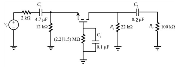
(a) Draw the low-frequency and midband equivalent circuits for the common-gate amplifier as shown. (b) What are the lower-cutoff frequency and midband gain of the amplifier if the Q-point=(0.1 mA, 8.6 V), VGS − VT N = 0.7 V, C1 = 4.7 ΩF, C2 = 0.2 μF, and C3 = 0.1 μF?

The low-frequency equivalent circuit for the CE amplifier is as shown below.
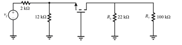
The mid-band equivalent circuit is as below.
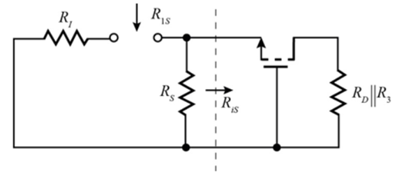
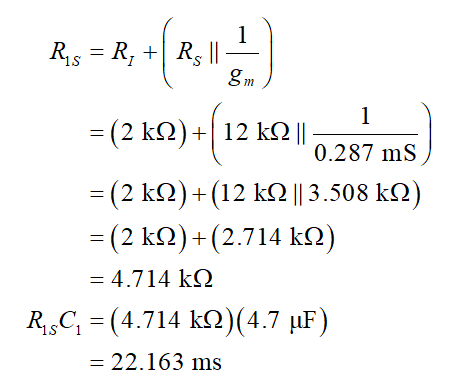
Short-circuit the capacitor C2 to calculate the resistance across the capacitor C1.
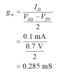
Calculate the value of transconductance.
Calculate the resistance.

Step by step
Solved in 10 steps with 10 images


