V₁ RI ww R2 TI V₂ T R3 R4

Related questions
Question
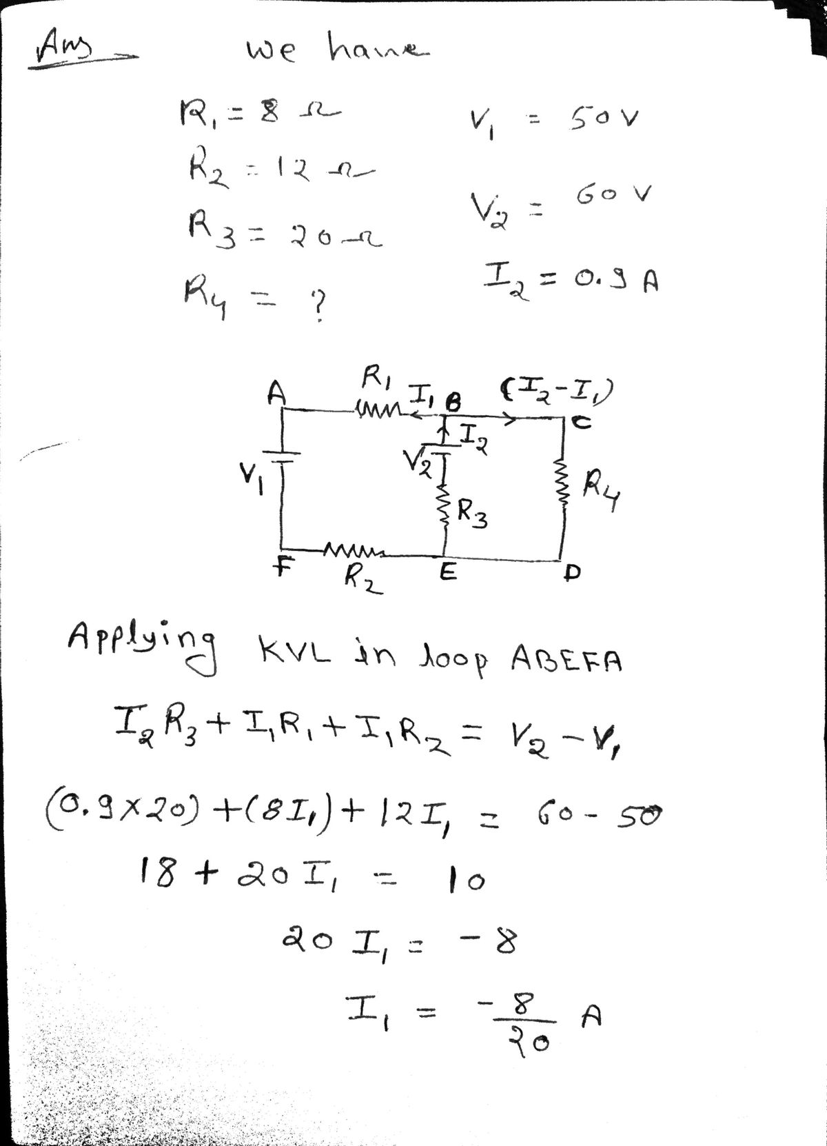
In the circuit below, find the resistance for R4. Known values are: R1= 8 ohms, R2= 12 homs, R3= 20 ohms, I2= 0.9A, V1= 50V and V2= 60V.

Transcribed Image Text:### Schematic Diagram: Series-Parallel Circuit
This diagram demonstrates an electrical circuit consisting of resistors, a voltage source, and current flow paths. Here’s a detailed explanation:
#### Components:
1. **Voltage Source (V₁):** The diagram indicates a primary voltage supply, labeled V₁, which provides the electrical potential driving the circuit.
2. **Resistors:**
- **R₁:** A resistor connected in series with the voltage source and other elements of the circuit.
- **R₂:** Another resistor placed in series after R₁.
- **R₃:** A resistor connected in parallel with V₂ in the middle portion of the circuit.
- **R₄:** A parallel resistor to the right of R₁.
3. **Current (I₂):** The direction of current flow through the parallel section of the circuit is indicated by an upward arrow labeled I₂.
4. **Voltage (V₂):** Represents the voltage across the parallel branch containing R₃.
#### Circuit Layout:
- The circuit starts from V₁, proceeds through R₁, then splits into two paths:
- One path continues straight through R₄.
- The other path flows downwards through R₃ and across V₂.
- The paths eventually reconvene and continue through R₂, completing the loop.
### Analysis:
- **Series Circuit Path:** Contains R₁ and R₂, where the total resistance is the sum of individual resistances (R₁ + R₂).
- **Parallel Circuit Path:** Consists of R₃ and R₄. The voltage across these resistors remains consistent, equal to V₂.
- **Total Resistance:** Calculated using the standard series-parallel resistance formula.
This diagram serves as a basic illustration for understanding series-parallel circuits in educational settings, where analyzing current flow, voltage distribution, and resistance calculation is crucial.
Expert Solution
Step 1

Step by step
Solved in 2 steps with 2 images
