The diodes D1 and D2 in this circuit are conducting with constant voltage drop VD = 0.7 V. Determine (1) Vo (2) I (3) IDI (4) ID2 D1 +10 V 4.65 ΚΩ D2 D₁ Σ 20 ΚΩ -10 V Vo
The diodes D1 and D2 in this circuit are conducting with constant voltage drop VD = 0.7 V. Determine (1) Vo (2) I (3) IDI (4) ID2 D1 +10 V 4.65 ΚΩ D2 D₁ Σ 20 ΚΩ -10 V Vo

Introductory Circuit Analysis (13th Edition)
13th Edition
ISBN:9780133923605
Author:Robert L. Boylestad
Publisher:Robert L. Boylestad
Chapter1: Introduction
Section: Chapter Questions
Problem 1P: Visit your local library (at school or home) and describe the extent to which it provides literature...

Related questions
Question
100%
1) please solve, will upvote if work is shown(:

Transcribed Image Text:**Diode Circuit Analysis**
The diodes D1 and D2 in this circuit are conducting with a constant voltage drop \( V_D = 0.7 \, \text{V} \). Determine the following:
1. \( V_o \) = ____________
2. \( I \) = ____________
3. \( I_{D1} \) = ____________
4. \( I_{D2} \) = ____________
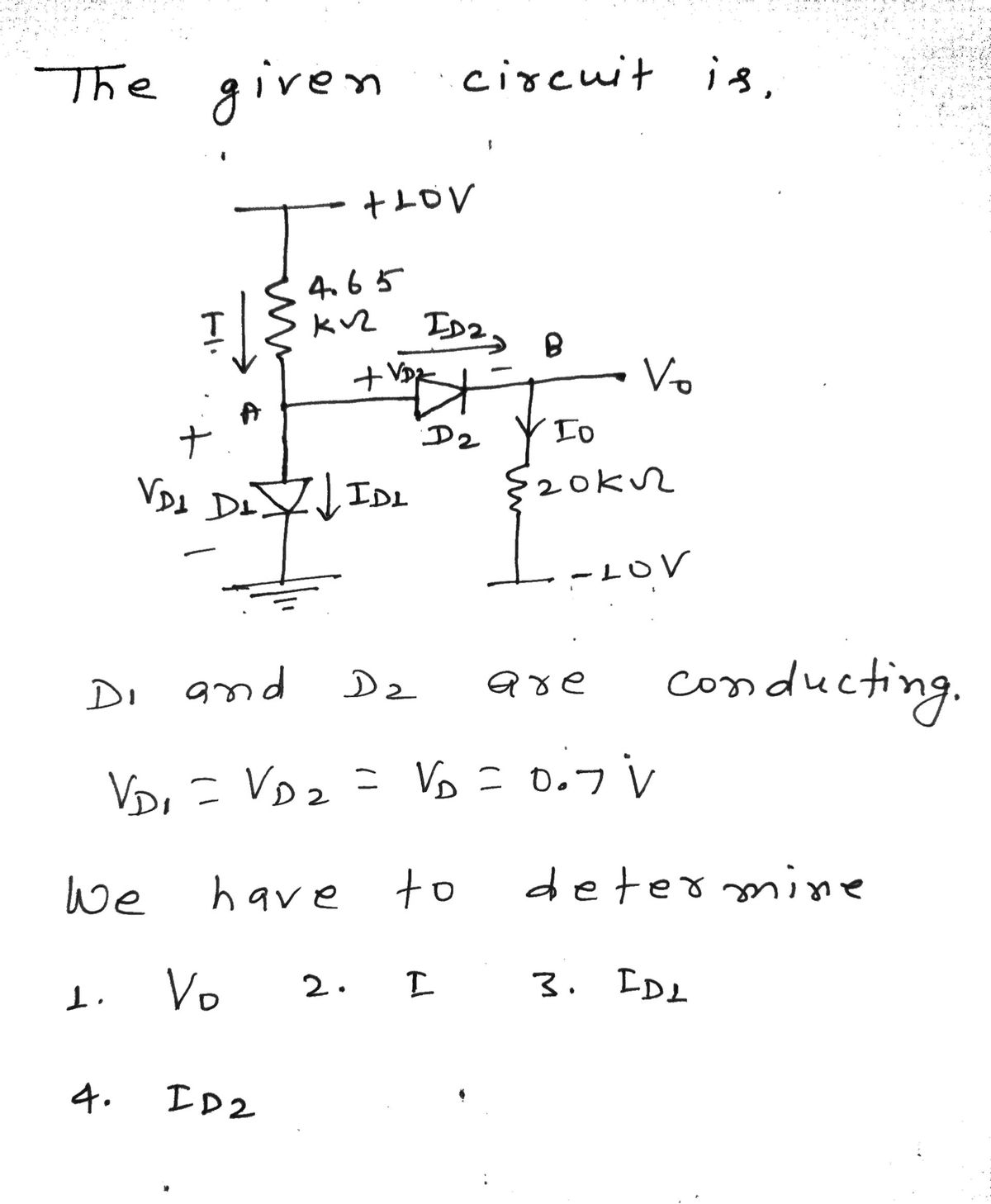
**Circuit Diagram Description:**
- The circuit features a voltage source of +10 V at the top and -10 V at the bottom.
- A 4.65 kΩ resistor is connected in series with a diode labeled D1.
- The anode of diode D1 is connected to the ground, and the cathode is connected to the junction point between the 4.65 kΩ resistor and diode D2.
- Diode D2 is oriented in the direction of current flow from the 4.65 kΩ resistor toward the output, Vo.
- A 20 kΩ resistor is connected between Vo and the -10 V supply.
- Current flows through both diodes and resistors as labeled in the diagram: \( I \) represents the current through the 4.65 kΩ resistor, \( I_{D1} \) for D1, and \( I_{D2} \) for D2.
Expert Solution
Step 1

Step by step
Solved in 3 steps with 3 images

Knowledge Booster


Learn more about
Need a deep-dive on the concept behind this application? Look no further. Learn more about this topic, electrical-engineering and related others by exploring similar questions and additional content below.Recommended textbooks for you
Introductory Circuit Analysis (13th Edition)
Electrical Engineering
ISBN:
9780133923605
Author:
Robert L. Boylestad
Publisher:
PEARSON

Delmar's Standard Textbook Of Electricity
Electrical Engineering
ISBN:
9781337900348
Author:
Stephen L. Herman
Publisher:
Cengage Learning

Programmable Logic Controllers
Electrical Engineering
ISBN:
9780073373843
Author:
Frank D. Petruzella
Publisher:
McGraw-Hill Education
Introductory Circuit Analysis (13th Edition)
Electrical Engineering
ISBN:
9780133923605
Author:
Robert L. Boylestad
Publisher:
PEARSON
Delmar's Standard Textbook Of Electricity
Electrical Engineering
ISBN:
9781337900348
Author:
Stephen L. Herman
Publisher:
Cengage Learning
Programmable Logic Controllers
Electrical Engineering
ISBN:
9780073373843
Author:
Frank D. Petruzella
Publisher:
McGraw-Hill Education

Fundamentals of Electric Circuits
Electrical Engineering
ISBN:
9780078028229
Author:
Charles K Alexander, Matthew Sadiku
Publisher:
McGraw-Hill Education

Electric Circuits. (11th Edition)
Electrical Engineering
ISBN:
9780134746968
Author:
James W. Nilsson, Susan Riedel
Publisher:
PEARSON

Engineering Electromagnetics
Electrical Engineering
ISBN:
9780078028151
Author:
Hayt, William H. (william Hart), Jr, BUCK, John A.
Publisher:
Mcgraw-hill Education,