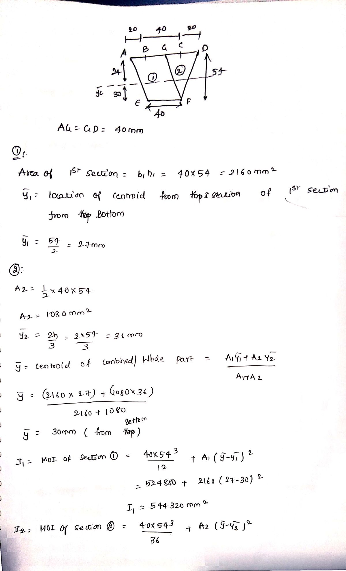
Q2. In the extruded profile shown in the figure, the maximum allowable stress in tension is 120 MPa and the maximum allowable stress in compression is 150 MPa . Find the maximum bending moment that can be applied to this profile. 20mm 40mm 20 mm 54mm ye 40mmm
Q2. In the extruded profile shown in the figure, the maximum allowable stress in tension is 120 MPa and the maximum allowable stress in compression is 150 MPa . Find the maximum bending moment that can be applied to this profile. 20mm 40mm 20 mm 54mm ye 40mmm

Elements Of Electromagnetics
7th Edition
ISBN:9780190698614
Author:Sadiku, Matthew N. O.
Publisher:Sadiku, Matthew N. O.
ChapterMA: Math Assessment
Section: Chapter Questions
Problem 1.1MA

Related questions
Question

Transcribed Image Text:**Question 2:**
In the extruded profile shown in the figure, the maximum allowable stress in tension is 120 MPa, and the maximum allowable stress in compression is 150 MPa. Find the maximum bending moment that can be applied to this profile.
**Figure Explanation:**
The diagram shows a trapezoidal profile with the following dimensions:
- Top width: 80 mm
- Bottom width: 40 mm
- Height: 54 mm
- Top edges extend 20 mm beyond the parallel sides
- Central axis (yc) marked for calculation purposes
**Accompanying Diagrams and Formulas:**
1. **Rectangular Area:**
- \( A = bh \)
- Centroid (C) located at the center
- Moment of Inertia:
- \( I_x = \frac{1}{12} bh^3 \)
- \( I_y = \frac{1}{12} hb^3 \)
2. **Triangular Area:**
- \( A = \frac{1}{2} bh \)
- Centroid (C) located at a distance of \( \frac{1}{3} h \) from the base
- Moment of Inertia:
- \( I_x = \frac{1}{36} bh^3 \)
This setup will generally be used to analyze the profile's moment of inertia and strength in relation to bending moments.
Expert Solution
Step 1

Trending now
This is a popular solution!

Step by step
Solved in 2 steps with 2 images

Knowledge Booster


Learn more about
Need a deep-dive on the concept behind this application? Look no further. Learn more about this topic, mechanical-engineering and related others by exploring similar questions and additional content below.Recommended textbooks for you
Elements Of Electromagnetics
Mechanical Engineering
ISBN:
9780190698614
Author:
Sadiku, Matthew N. O.
Publisher:
Oxford University Press

Mechanics of Materials (10th Edition)
Mechanical Engineering
ISBN:
9780134319650
Author:
Russell C. Hibbeler
Publisher:
PEARSON

Thermodynamics: An Engineering Approach
Mechanical Engineering
ISBN:
9781259822674
Author:
Yunus A. Cengel Dr., Michael A. Boles
Publisher:
McGraw-Hill Education
Elements Of Electromagnetics
Mechanical Engineering
ISBN:
9780190698614
Author:
Sadiku, Matthew N. O.
Publisher:
Oxford University Press
Mechanics of Materials (10th Edition)
Mechanical Engineering
ISBN:
9780134319650
Author:
Russell C. Hibbeler
Publisher:
PEARSON
Thermodynamics: An Engineering Approach
Mechanical Engineering
ISBN:
9781259822674
Author:
Yunus A. Cengel Dr., Michael A. Boles
Publisher:
McGraw-Hill Education

Control Systems Engineering
Mechanical Engineering
ISBN:
9781118170519
Author:
Norman S. Nise
Publisher:
WILEY

Mechanics of Materials (MindTap Course List)
Mechanical Engineering
ISBN:
9781337093347
Author:
Barry J. Goodno, James M. Gere
Publisher:
Cengage Learning

Engineering Mechanics: Statics
Mechanical Engineering
ISBN:
9781118807330
Author:
James L. Meriam, L. G. Kraige, J. N. Bolton
Publisher:
WILEY