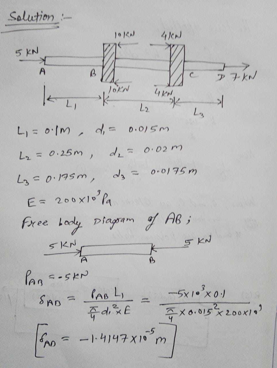
Problem 2: Consider the two gears mounted on the shaft, as shown. Distances are L; = 100 mm, L; = 250 mm, and Ly = 175 mm. Diameter of shaft AB is 15 mm, diameter of shaft BC is 20 mm, and diameter of shaft CD is 17.5 mm. Young's modulus for each portion is 200 GPa. Determine the displacement of point D with reference to point A. Also, determine the displacement of point A relative to C. b. Determine the axial strain at any point in shaft segments AB, BC and CD, respectively. If Poisson's ratio for the material of the shafts is v = 0.2, determine the lateral strain in each of the shaft segments. "p Based on your answers to part (a), do the gears move towards each other, or do they separate from each other? Note that in real gearboxes, movement of gears towards or away from each other is prevented by using thrust bearings. 10 kN 4 kN 5 kN 7 kN 10 kN 4 kN
Problem 2: Consider the two gears mounted on the shaft, as shown. Distances are L; = 100 mm, L; = 250 mm, and Ly = 175 mm. Diameter of shaft AB is 15 mm, diameter of shaft BC is 20 mm, and diameter of shaft CD is 17.5 mm. Young's modulus for each portion is 200 GPa. Determine the displacement of point D with reference to point A. Also, determine the displacement of point A relative to C. b. Determine the axial strain at any point in shaft segments AB, BC and CD, respectively. If Poisson's ratio for the material of the shafts is v = 0.2, determine the lateral strain in each of the shaft segments. "p Based on your answers to part (a), do the gears move towards each other, or do they separate from each other? Note that in real gearboxes, movement of gears towards or away from each other is prevented by using thrust bearings. 10 kN 4 kN 5 kN 7 kN 10 kN 4 kN
Elements Of Electromagnetics
7th Edition
ISBN:9780190698614
Author:Sadiku, Matthew N. O.
Publisher:Sadiku, Matthew N. O.
ChapterMA: Math Assessment
Section: Chapter Questions
Problem 1.1MA
Related questions
Question

Transcribed Image Text:**Problem 2:**
Consider the two gears mounted on the shaft, as shown.
- Distance \(L_1 = 300 \, \text{mm}, \, L_2 = 250 \, \text{mm}, \, L_3 = 175 \, \text{mm}\).
- Diameter of shaft AB is \(20 \, \text{mm}\), and diameter of shaft CD is \(15 \, \text{mm}\).
- Young's modulus for each portion is \(200 \, \text{GPa}\).
**Tasks:**
a. Determine the displacement of point A relative to point B and also determine the displacement of point A relative to C.
b. Determine the axial strain at any point in shaft segments AB, BC, and CD respectively.
c. Determine the lateral strain in each of the shaft segments.
d. Poisson's ratio for the material of the shaft is \(\nu = 0.2\).
The axial forces acting on the shaft are:
- At point A: \(5 \, \text{kN}\) upwards
- At point B: \(10 \, \text{kN}\) downwards
- At point C: \(4 \, \text{kN}\) upwards
- At point D: \(7 \, \text{kN}\) upwards
These forces are distributed along the segments of the shaft with different diameters. Note that the axial movement of gears towards or away from each other is prevented by using thrust bearings.
**Diagram Explanation:**
The diagram shows a vertical shaft with forces acting along different segments.
- **Segment AB**: The topmost section with forces acting upward at A and downward at B.
- **Segment BC**: Middle section connected by gears.
- **Segment CD**: Bottom section with a force acting upward at D.
This setup is a typical problem in mechanical engineering to find displacements and strains in shaft segments under given forces.
Expert Solution
Step 1

Trending now
This is a popular solution!
Step by step
Solved in 5 steps with 5 images

Recommended textbooks for you

Elements Of Electromagnetics
Mechanical Engineering
ISBN:
9780190698614
Author:
Sadiku, Matthew N. O.
Publisher:
Oxford University Press

Mechanics of Materials (10th Edition)
Mechanical Engineering
ISBN:
9780134319650
Author:
Russell C. Hibbeler
Publisher:
PEARSON

Thermodynamics: An Engineering Approach
Mechanical Engineering
ISBN:
9781259822674
Author:
Yunus A. Cengel Dr., Michael A. Boles
Publisher:
McGraw-Hill Education

Elements Of Electromagnetics
Mechanical Engineering
ISBN:
9780190698614
Author:
Sadiku, Matthew N. O.
Publisher:
Oxford University Press

Mechanics of Materials (10th Edition)
Mechanical Engineering
ISBN:
9780134319650
Author:
Russell C. Hibbeler
Publisher:
PEARSON

Thermodynamics: An Engineering Approach
Mechanical Engineering
ISBN:
9781259822674
Author:
Yunus A. Cengel Dr., Michael A. Boles
Publisher:
McGraw-Hill Education

Control Systems Engineering
Mechanical Engineering
ISBN:
9781118170519
Author:
Norman S. Nise
Publisher:
WILEY

Mechanics of Materials (MindTap Course List)
Mechanical Engineering
ISBN:
9781337093347
Author:
Barry J. Goodno, James M. Gere
Publisher:
Cengage Learning

Engineering Mechanics: Statics
Mechanical Engineering
ISBN:
9781118807330
Author:
James L. Meriam, L. G. Kraige, J. N. Bolton
Publisher:
WILEY