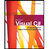
Interface (do not edit the content inside this box) Inputs Outputs Rotatee: 0 1 0 0 inA, A, 4A, 0, 04 Rotation amount in8, 4 0 nB, D 0 inB, in8, 0 Result of Rotating input A by the amount given by input B DO out3 DO out2 Figure: lab2_part1.dig Interface DO out! DO outo input Note how both the 2 tunnels in the circuit have the same name "wire". This signifies electrical connectivity input D out Figure: playWithTunnels.dig screenshot


Specifications: Part-1
Part-1: Description
In this part of the lab you will build a single operation ALU. This ALU will implement a bitwise left rotation. For
this lab assignment you are not allowed to use Digital's Arithmetic components.
IF YOU ARE FOUND USING THEM, YOU WILL RECEIVE A ZERO FOR LAB2!
The ALU you will be implementing consists of two 4-bit inputs (named inA and inB) and one 4-bit output (named
out). Your ALU must rotate the bits in inA by the amount given by inB (i.e. 0-15).
Part-1: User Interface
You are provided an interface file lab2_part1.dig; start Part-1 from this file.
NOTE: You are not permitted to edit the content inside the dotted lines rectangle.Part-1: Example
In the figure above, the input values that we have selected to test are inA = {inA_3, inA_2, inA_1, inA_0} = {0, 1, 0,
0} and inB = {inB_3, inB_2, inB_1, inB_0} = {0, 0, 1, 0}. Therefore, we must rotate the bus 0100 bitwise left by
00102, or 2 in base 10, to get {0, 0, 0, 1}. Please note that a rotation left is not the same thing as a shift left (which
many newcomers are apt to confuse)!
When you open the lab2_part1.dig file, you will of course not see these exact values in green because that is what we
used to verify your circuit correctly working by clicking on the Simulate button. On your end, you should go through
all possible test cases to verify your design works. Make sure to name all the wires and input/outputs correctly so
that they match the test interface names within lab2_part1.dig. You will need to do the same for part2 and part 3
as well.
Hint: Using Multiplexers will help you out a lot here.
To help you make sure you are testing your rotation results left, you can try using the included rotate_left.cpp C++
program for verification. Modify the values of the array arr elements and the rotation value rotateBy. If you don’t
have a C++ compiler on your local machine, try running the code in onlinegdb.
The “Tunnel” component in Digital for Lab2
In Lab1, you might have noticed how much effort it took to draw so many inputs and wire them all over the place
without unintentionally connecting them to the incorrect outputs and nodes! Turns out, Digital does provide some
means to help reduce this burden.
This manifests as the Tunnel component. Go to Components->Wires->Tunnel. The symbol looks like a triangle with
one vertex being a dot. The idea is that instead of extending your wires physically all over your circuit drawing space
by drawing them as lines, you can use tunnels as placeholders in different locations on your diagram for the same
wire. These tunnels must have the same name so as to symbolize the same electrical connection. You c an rotate the
tunnel, to align it like any other symbol with the ‘r’ hot key. See the Digital Cheat Sheet under Pages for more hints.
You are provided the file playWithTunnels.dig to give you an idea of how tunnels work in Digital. Think of them as
being like wormholes that can connect 2 physically separate points on your circuit diagram through the same wire
connection.Note that all the Interface areas in the .dig files for part1, part2 and part3 have tunnel components in them. That
means when you draw your circuit outside the interface box in these files, you will need to draw the appropriate
number of tunnel wires which hook up (via wormholes!) to the provided inputs and outputs within the interface box.
Make sure the tunnels have the correct wire names.


Step by step
Solved in 2 steps with 1 images