For the circuit shown below (B1 150), détermine: - 1. the de values (Va1, V82, Vc1. Vcz, VE1, VE2, VCE1, VCE2).
For the circuit shown below (B1 150), détermine: - 1. the de values (Va1, V82, Vc1. Vcz, VE1, VE2, VCE1, VCE2).

Introductory Circuit Analysis (13th Edition)
13th Edition
ISBN:9780133923605
Author:Robert L. Boylestad
Publisher:Robert L. Boylestad
Chapter1: Introduction
Section: Chapter Questions
Problem 1P: Visit your local library (at school or home) and describe the extent to which it provides literature...

Related questions
Question

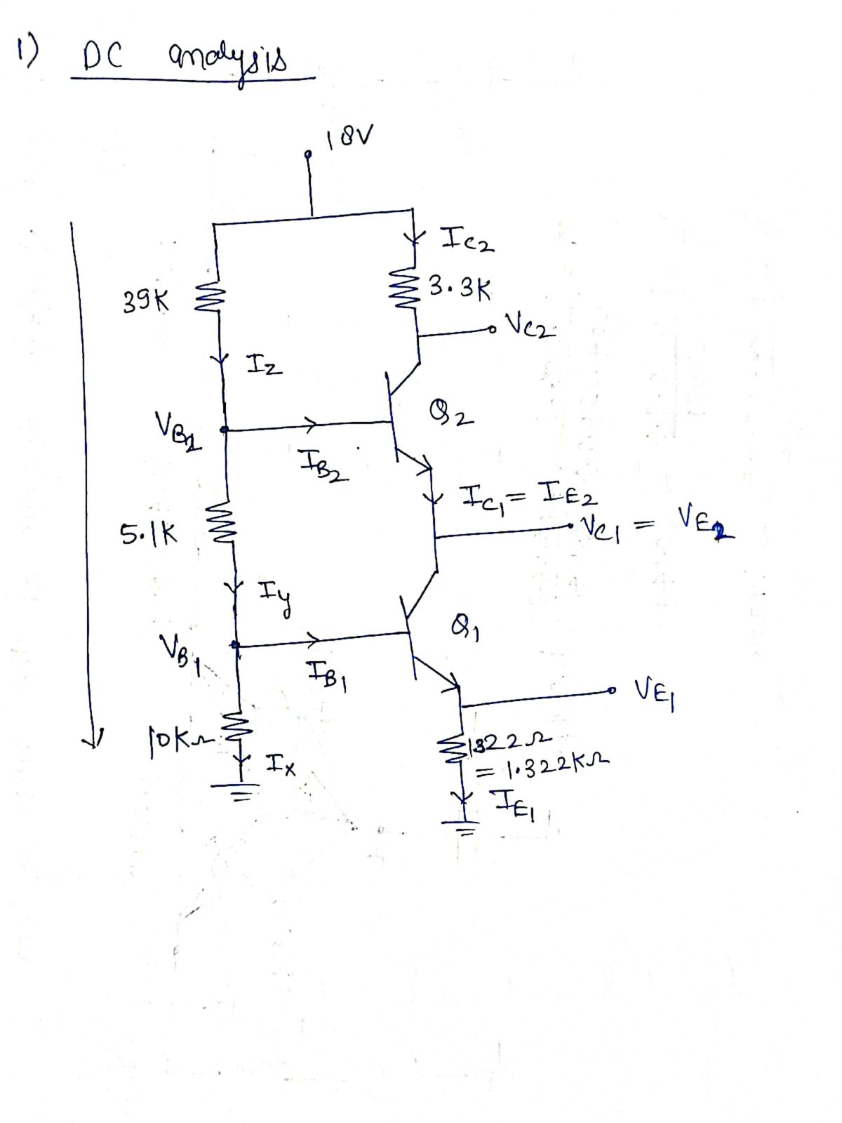
Transcribed Image Text:For the circuit shown below (B1-62-150), determine: -
1. the de values (V81, V82, Vc1. Vcz, VE1. VE2, VCE1, VCE2).
2. The Zt, Zo, A, NL. Ap L. Ays.
-7
Vcc 18 V
R 39 ka
Rc $3.3 ka
V
Q Ven
R34.7 kn
R: 35.1 kn
1 kn
Rs
R, 310 kn
RE22 Ω
Ra१1.3 kn
Expert Solution
Step 1
Since you have posted a question with multiple sub-parts, we will solve 1st question with all subparts for you. To get remaining solution, please repost the complete question and mention the sub-parts to be solved".

Step by step
Solved in 4 steps with 4 images

Recommended textbooks for you
Introductory Circuit Analysis (13th Edition)
Electrical Engineering
ISBN:
9780133923605
Author:
Robert L. Boylestad
Publisher:
PEARSON

Delmar's Standard Textbook Of Electricity
Electrical Engineering
ISBN:
9781337900348
Author:
Stephen L. Herman
Publisher:
Cengage Learning

Programmable Logic Controllers
Electrical Engineering
ISBN:
9780073373843
Author:
Frank D. Petruzella
Publisher:
McGraw-Hill Education
Introductory Circuit Analysis (13th Edition)
Electrical Engineering
ISBN:
9780133923605
Author:
Robert L. Boylestad
Publisher:
PEARSON
Delmar's Standard Textbook Of Electricity
Electrical Engineering
ISBN:
9781337900348
Author:
Stephen L. Herman
Publisher:
Cengage Learning
Programmable Logic Controllers
Electrical Engineering
ISBN:
9780073373843
Author:
Frank D. Petruzella
Publisher:
McGraw-Hill Education

Fundamentals of Electric Circuits
Electrical Engineering
ISBN:
9780078028229
Author:
Charles K Alexander, Matthew Sadiku
Publisher:
McGraw-Hill Education

Electric Circuits. (11th Edition)
Electrical Engineering
ISBN:
9780134746968
Author:
James W. Nilsson, Susan Riedel
Publisher:
PEARSON

Engineering Electromagnetics
Electrical Engineering
ISBN:
9780078028151
Author:
Hayt, William H. (william Hart), Jr, BUCK, John A.
Publisher:
Mcgraw-hill Education,