Calculate the Resultant Condition of the HOLE in the drawing below: 1.000 O 1.060 O 1.000 O.530 0.982 C 2.000 Ø.995-1.000 01.005-1.030 +0.008MABC +0.005MABC 6.00 O None of these answers is correct X 3.000 O B A .XX = .01 ANGLES = + 1°
Calculate the Resultant Condition of the HOLE in the drawing below: 1.000 O 1.060 O 1.000 O.530 0.982 C 2.000 Ø.995-1.000 01.005-1.030 +0.008MABC +0.005MABC 6.00 O None of these answers is correct X 3.000 O B A .XX = .01 ANGLES = + 1°

Elements Of Electromagnetics
7th Edition
ISBN:9780190698614
Author:Sadiku, Matthew N. O.
Publisher:Sadiku, Matthew N. O.
ChapterMA: Math Assessment
Section: Chapter Questions
Problem 1.1MA

Related questions

Question

Transcribed Image Text:**Title: Understanding Resultant Condition of the HOLE**
**Objective:**
Learn how to calculate the resultant condition of a hole in a mechanical drawing based on given tolerances.
---
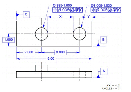
**Diagram Explanation:**
The diagram presents a rectangular part with two circular holes. Key features include:
1. **Dimensions:**
- The overall length of the part is 6.000 units.
- Two holes are aligned horizontally, each with a distance of 2.000 units from the left edge and the same 3.000 unit distance between them.
2. **Hole Specifications:**
- Left Hole: Diameter ranges from 0.995 to 1.000 units, with a positional tolerance of Ø0.008 at maximum material condition (MMC), referencing datum points A, B, and C.
- Right Hole: Diameter ranges from 1.005 to 1.030 units, with a positional tolerance of Ø0.005 at MMC, referencing the same datum points.
3. **Datums:**
- Datum A (Top view): Located at the bottom of the rectangle.
- Datum B and C (Side view): Located on the ends of the rectangle, indicating vertical and horizontal reference planes.
4. **Standard Tolerances:**
- Linear dimensions have a general tolerance of ±0.01 units.
- Angular dimensions have a tolerance of ±1 degree.
---
**Question:**
Calculate the resultant condition of the HOLE in the drawing using the specified options.
**Answer Choices:**
- 1.060
- 1.000
- 0.530
- 0.982
- None of these answers is correct
Understanding this diagram requires knowledge of geometric dimensioning and tolerancing (GD&T) to correctly interpret and calculate the resultant conditions of geometric features.
Expert Solution
Step 1
Draw the given diagram for the hole.

Step by step
Solved in 2 steps with 1 images

Knowledge Booster


Learn more about
Need a deep-dive on the concept behind this application? Look no further. Learn more about this topic, mechanical-engineering and related others by exploring similar questions and additional content below.Recommended textbooks for you
Elements Of Electromagnetics
Mechanical Engineering
ISBN:
9780190698614
Author:
Sadiku, Matthew N. O.
Publisher:
Oxford University Press

Mechanics of Materials (10th Edition)
Mechanical Engineering
ISBN:
9780134319650
Author:
Russell C. Hibbeler
Publisher:
PEARSON

Thermodynamics: An Engineering Approach
Mechanical Engineering
ISBN:
9781259822674
Author:
Yunus A. Cengel Dr., Michael A. Boles
Publisher:
McGraw-Hill Education
Elements Of Electromagnetics
Mechanical Engineering
ISBN:
9780190698614
Author:
Sadiku, Matthew N. O.
Publisher:
Oxford University Press
Mechanics of Materials (10th Edition)
Mechanical Engineering
ISBN:
9780134319650
Author:
Russell C. Hibbeler
Publisher:
PEARSON
Thermodynamics: An Engineering Approach
Mechanical Engineering
ISBN:
9781259822674
Author:
Yunus A. Cengel Dr., Michael A. Boles
Publisher:
McGraw-Hill Education

Control Systems Engineering
Mechanical Engineering
ISBN:
9781118170519
Author:
Norman S. Nise
Publisher:
WILEY

Mechanics of Materials (MindTap Course List)
Mechanical Engineering
ISBN:
9781337093347
Author:
Barry J. Goodno, James M. Gere
Publisher:
Cengage Learning

Engineering Mechanics: Statics
Mechanical Engineering
ISBN:
9781118807330
Author:
James L. Meriam, L. G. Kraige, J. N. Bolton
Publisher:
WILEY