Calcuate Torsion From Point A to Point C and Bending from Point A to Point B and from Point A to Point C. Draw a FBD from point A to point B and another for point A to C indicating what stresses are been calculate. Use the stress tensor and stress cube to Indicate what forces are acting at point A. Force apply at point B is 70lb Distacen from Point A to B is 12 in or 1 feet long Distacen from Point A to C is 3 in Handle diameter 0.625 in
Calcuate Torsion From Point A to Point C and Bending from Point A to Point B and from Point A to Point C. Draw a FBD from point A to point B and another for point A to C indicating what stresses are been calculate. Use the stress tensor and stress cube to Indicate what forces are acting at point A. Force apply at point B is 70lb Distacen from Point A to B is 12 in or 1 feet long Distacen from Point A to C is 3 in Handle diameter 0.625 in

Elements Of Electromagnetics
7th Edition
ISBN:9780190698614
Author:Sadiku, Matthew N. O.
Publisher:Sadiku, Matthew N. O.
ChapterMA: Math Assessment
Section: Chapter Questions
Problem 1.1MA

Related questions
Question
100%
Calcuate Torsion From Point A to Point C and Bending from Point A to Point B and from Point A to Point C. Draw a FBD from point A to point B and another for point A to C indicating what stresses are been calculate. Use the stress tensor and stress cube to Indicate what forces are acting at point A.
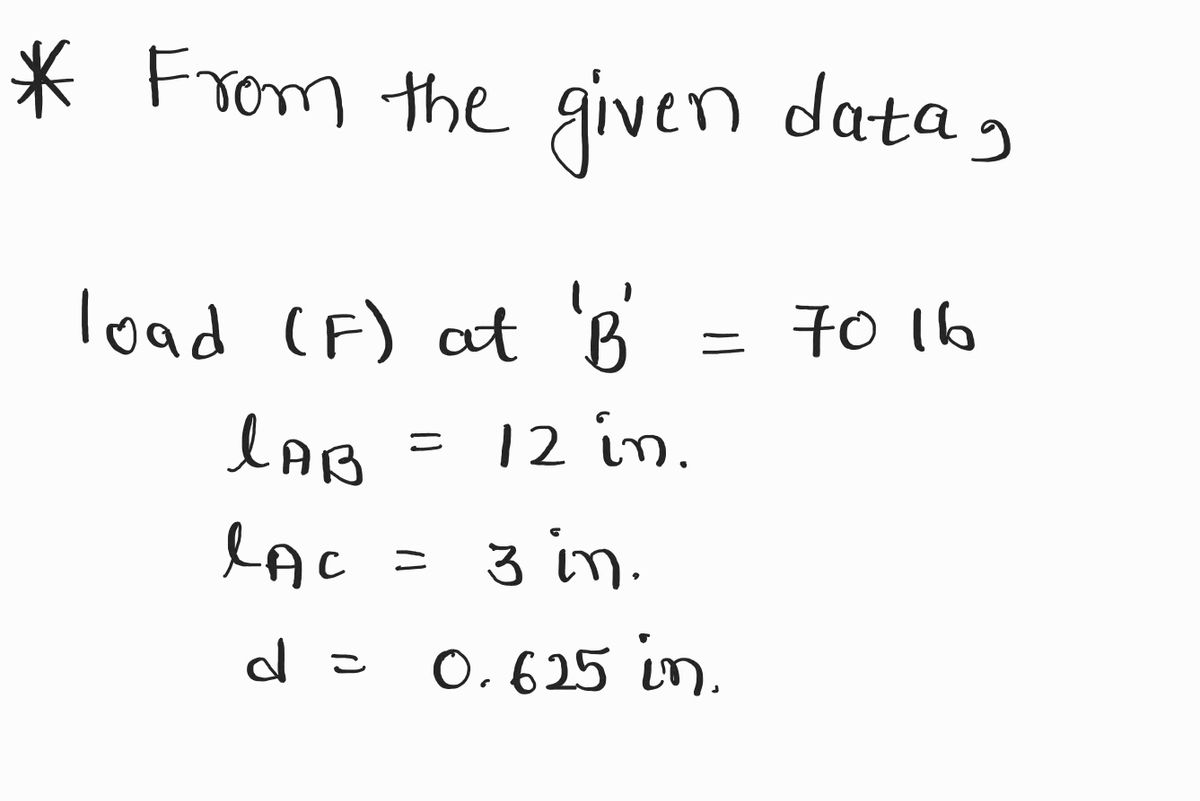
Force apply at point B is 70lb
Distacen from Point A to B is 12 in or 1 feet long
Distacen from Point A to C is 3 in
Handle diameter 0.625 in

Transcribed Image Text:**Image Transcription and Explanation:**
This illustration showcases the mechanics of using a lug wrench to apply force to a tire axle.
**Top Diagram:**
- **Components:**
- The diagram features a horizontal representation of a wheel with an axle at its center.
- A lug wrench is depicted as a bent tool with endpoints labeled as "A" and "B."
- **Measurements:**
- The distance from point "A" to the axle is marked as "3 in" (inches).
- **Mechanics:**
- The lug wrench is shown applying force at point "B."
**Bottom Diagram:**
- **Components:**
- A tire is shown with bolts around the axle.
- A red arrow labeled "F" indicates the direction of the force applied by the lug wrench.
- **Mechanics:**
- The lug wrench is inserted into a bolt, showing force "F" applied perpendicular to the wrench.
- The force is transferred to the bolts, aiding in the removal or tightening process.
This visual aid is designed to help explain the physical principles of levers and torque as applied in mechanical tasks such as changing a tire.
Expert Solution
Step 1: Given data
For the solution refer below images.
- Find F.B.D. and shear and bending diagrams for portions AB and BC.
- Find stress tensor at A.

Step by step
Solved in 5 steps with 7 images

Knowledge Booster


Learn more about
Need a deep-dive on the concept behind this application? Look no further. Learn more about this topic, mechanical-engineering and related others by exploring similar questions and additional content below.Recommended textbooks for you
Elements Of Electromagnetics
Mechanical Engineering
ISBN:
9780190698614
Author:
Sadiku, Matthew N. O.
Publisher:
Oxford University Press

Mechanics of Materials (10th Edition)
Mechanical Engineering
ISBN:
9780134319650
Author:
Russell C. Hibbeler
Publisher:
PEARSON

Thermodynamics: An Engineering Approach
Mechanical Engineering
ISBN:
9781259822674
Author:
Yunus A. Cengel Dr., Michael A. Boles
Publisher:
McGraw-Hill Education
Elements Of Electromagnetics
Mechanical Engineering
ISBN:
9780190698614
Author:
Sadiku, Matthew N. O.
Publisher:
Oxford University Press
Mechanics of Materials (10th Edition)
Mechanical Engineering
ISBN:
9780134319650
Author:
Russell C. Hibbeler
Publisher:
PEARSON
Thermodynamics: An Engineering Approach
Mechanical Engineering
ISBN:
9781259822674
Author:
Yunus A. Cengel Dr., Michael A. Boles
Publisher:
McGraw-Hill Education

Control Systems Engineering
Mechanical Engineering
ISBN:
9781118170519
Author:
Norman S. Nise
Publisher:
WILEY

Mechanics of Materials (MindTap Course List)
Mechanical Engineering
ISBN:
9781337093347
Author:
Barry J. Goodno, James M. Gere
Publisher:
Cengage Learning

Engineering Mechanics: Statics
Mechanical Engineering
ISBN:
9781118807330
Author:
James L. Meriam, L. G. Kraige, J. N. Bolton
Publisher:
WILEY