Y Part B - Clockwise Rotation of a Stress Element with Only One Normal Stress The state of stress at a point in a member is shown on the rectangular stress element in (Eigure 4) where the magnitudes of the stresses are lo₂-149 MPa and Tay - 49 MPa Determine the state of stress on an element rotated 65° clockwise from the element shown Express your answers, separated by commas, to three significant figures. View Available Hint(s) 0,0 Taly Submit IVE ΑΣΦ ↓↑ vec Part C Counterclockide 3 → C CARIC ? MPa, MPa, MPa 6 2 W Figure 0₂ < 4 of 6 >
Y Part B - Clockwise Rotation of a Stress Element with Only One Normal Stress The state of stress at a point in a member is shown on the rectangular stress element in (Eigure 4) where the magnitudes of the stresses are lo₂-149 MPa and Tay - 49 MPa Determine the state of stress on an element rotated 65° clockwise from the element shown Express your answers, separated by commas, to three significant figures. View Available Hint(s) 0,0 Taly Submit IVE ΑΣΦ ↓↑ vec Part C Counterclockide 3 → C CARIC ? MPa, MPa, MPa 6 2 W Figure 0₂ < 4 of 6 >

Elements Of Electromagnetics
7th Edition
ISBN:9780190698614
Author:Sadiku, Matthew N. O.
Publisher:Sadiku, Matthew N. O.
ChapterMA: Math Assessment
Section: Chapter Questions
Problem 1.1MA

Related questions
Question
Please work out part A and B

Transcribed Image Text:# Clockwise Rotation of a Stress Element with Only One Normal Stress
### Part B
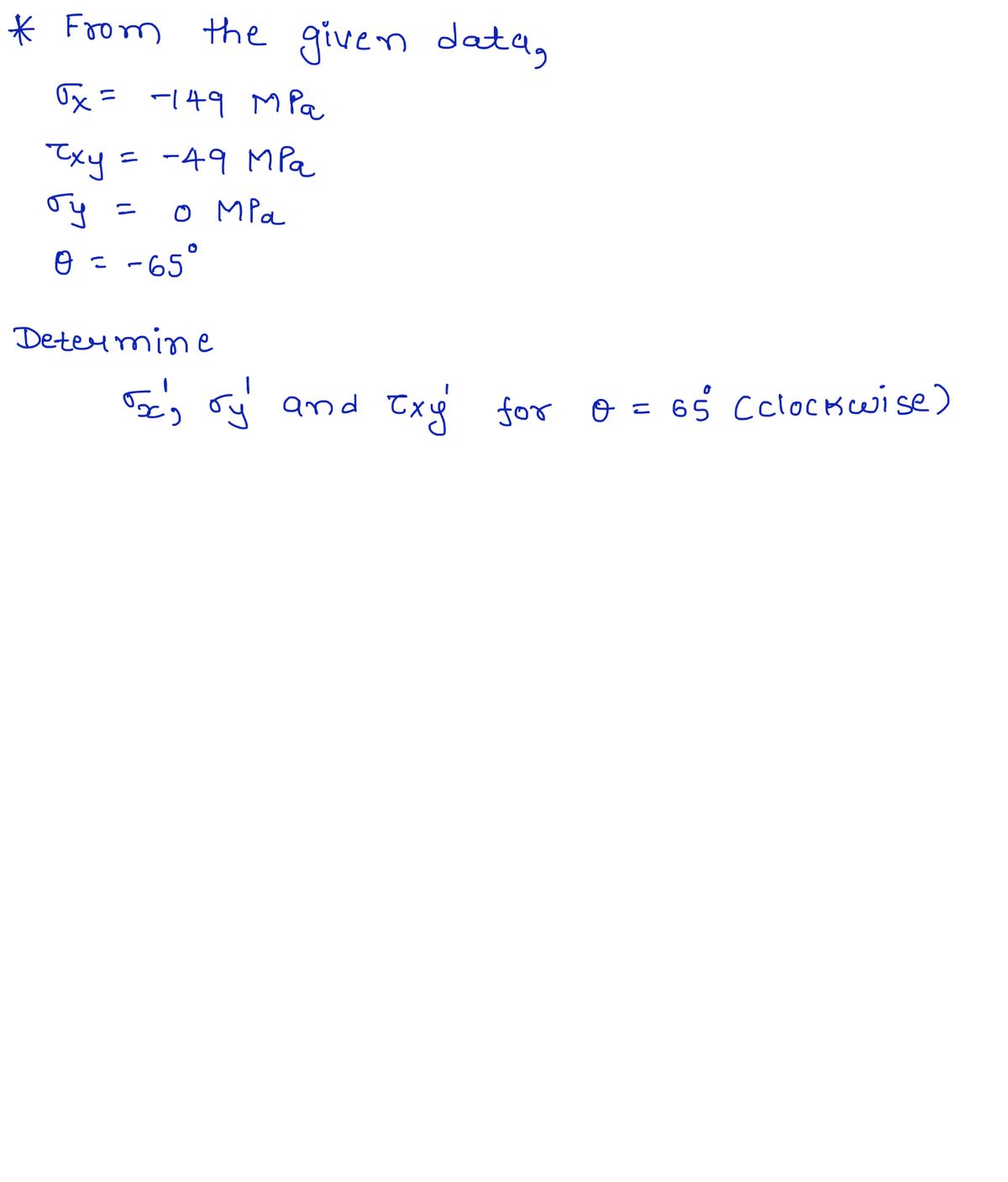
The state of stress at a point in a member is shown on the rectangular stress element in **Figure 4**, where the magnitudes of the stresses are:
- \(\sigma_x = 149 \, \text{MPa}\)
- \(\tau_{xy} = 49 \, \text{MPa}\)
Determine the state of stress on an element rotated \(65^\circ\) clockwise from the element shown.
**Express your answers, separated by commas, to three significant figures.**
#### Input Hint Area
A blank input area is provided for entering the values of rotated stress in the given format:
- Units expected: \(\text{MPa}\)
### Diagram Explanation
#### Figure Description
The figure on the right illustrates a rectangular stress element.
- **Orientation**: The rectangle represents a stress element on which stresses are acting.
- **Stress Notation**:
- \(\sigma_x\) is acting horizontally on the right side of the element.
- \(\tau_{xy}\) is a shear stress, acting vertically on the top and bottom sides of the element.
The diagram visually represents the stresses applied and is used to determine the rotated stress configuration after a \(65^\circ\) clockwise rotation.

Transcribed Image Text:### Part A - State of Stress on an Inclined Plane
The state of stress at a point in a member is shown on the rectangular stress element in (Figure 3). The magnitudes of the stresses are:
- \(\sigma_x = 100 \, \text{MPa}\)
- \(\sigma_y = 35 \, \text{MPa}\)
- |\(\tau_{xy}\)| = 49 MPa
Using the stress-transformation equations, determine the state of stress on the inclined plane \(AB\).
**Express your answers**, separated by a comma, to three significant figures.
#### Input Box
- \( \sigma_x' = \tau_{xy}' \)
(MPa, MPa)
#### Attempt Feedback
- Incorrect; Try Again; 3 attempts remaining
---
### Part B - Clockwise Rotation of a Stress Element with Only One Normal Stress
---
### Figure Explanation
The figure illustrates a rectangular stress element rotated on an inclined plane. Key features include:
- **Rectangular Stress Element**: The shape is depicted in a tan color.
- **Inclined Plane**: Indicated by \(AB\), tilted at angles 60° and 15° relative to the horizontal plane.
- **Stress Components**:
- \(\sigma_x'\) and \(\sigma_y'\): Normal stress components on the inclined plane.
- \(\tau_{xy}\): Shear stress on the plane.
- **Angles**: The diagram shows angles to define the orientation of the stresses.
The purpose of the figure is to visualize the transformation of stress components when the plane is inclined from its original orientation.
Expert Solution
Step 1: Write the given data with suitable variables-
Note:- As per honor code and answering guidelines I can answer 1st question at a time.If you want other please post it separately.

Step by step
Solved in 3 steps with 3 images

Knowledge Booster


Learn more about
Need a deep-dive on the concept behind this application? Look no further. Learn more about this topic, mechanical-engineering and related others by exploring similar questions and additional content below.Recommended textbooks for you
Elements Of Electromagnetics
Mechanical Engineering
ISBN:
9780190698614
Author:
Sadiku, Matthew N. O.
Publisher:
Oxford University Press

Mechanics of Materials (10th Edition)
Mechanical Engineering
ISBN:
9780134319650
Author:
Russell C. Hibbeler
Publisher:
PEARSON

Thermodynamics: An Engineering Approach
Mechanical Engineering
ISBN:
9781259822674
Author:
Yunus A. Cengel Dr., Michael A. Boles
Publisher:
McGraw-Hill Education
Elements Of Electromagnetics
Mechanical Engineering
ISBN:
9780190698614
Author:
Sadiku, Matthew N. O.
Publisher:
Oxford University Press
Mechanics of Materials (10th Edition)
Mechanical Engineering
ISBN:
9780134319650
Author:
Russell C. Hibbeler
Publisher:
PEARSON
Thermodynamics: An Engineering Approach
Mechanical Engineering
ISBN:
9781259822674
Author:
Yunus A. Cengel Dr., Michael A. Boles
Publisher:
McGraw-Hill Education

Control Systems Engineering
Mechanical Engineering
ISBN:
9781118170519
Author:
Norman S. Nise
Publisher:
WILEY

Mechanics of Materials (MindTap Course List)
Mechanical Engineering
ISBN:
9781337093347
Author:
Barry J. Goodno, James M. Gere
Publisher:
Cengage Learning

Engineering Mechanics: Statics
Mechanical Engineering
ISBN:
9781118807330
Author:
James L. Meriam, L. G. Kraige, J. N. Bolton
Publisher:
WILEY