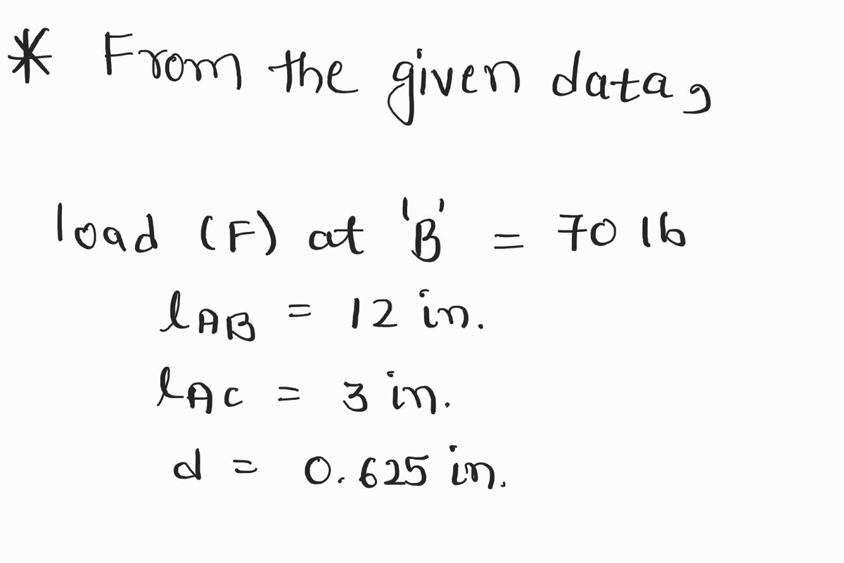
Calcuate Shear and Bending From Point A to Point B and Point A to Point C. Draw a FBD from point A to point B and another for point A to C indicating what stresses are been calculate. Use the stress tensor and stress cube to Indicate what forces are acting at point A. Force apply at point B is 70lb Distacen from Point A to B is 12 in or 1 feet long Distacen from Point A to C is 3 in Handle diameter 0.625 in
Calcuate Shear and Bending From Point A to Point B and Point A to Point C. Draw a FBD from point A to point B and another for point A to C indicating what stresses are been calculate. Use the stress tensor and stress cube to Indicate what forces are acting at point A. Force apply at point B is 70lb Distacen from Point A to B is 12 in or 1 feet long Distacen from Point A to C is 3 in Handle diameter 0.625 in
Elements Of Electromagnetics
7th Edition
ISBN:9780190698614
Author:Sadiku, Matthew N. O.
Publisher:Sadiku, Matthew N. O.
ChapterMA: Math Assessment
Section: Chapter Questions
Problem 1.1MA
Related questions
Question
Calcuate Shear and Bending From Point A to Point B and Point A to Point C. Draw a FBD from point A to point B and another for point A to C indicating what stresses are been calculate. Use the stress tensor and stress cube to Indicate what forces are acting at point A.
Force apply at point B is 70lb
Distacen from Point A to B is 12 in or 1 feet long
Distacen from Point A to C is 3 in
Handle diameter 0.625 in

Transcribed Image Text:### Image Transcription and Analysis
#### Diagram Explanation
The image consists of two diagrams illustrating the use of a lug wrench for a tire-changing process:
1. **Top Diagram: Cross-Sectional Side View**
- **Axle**: Shown at the top surrounded by the wheel structure.
- **Lug Wrench**: A tool depicted in a red color, labeled 'A' and 'B'.
- **Position**: The wrench forms an L-shape, with the handle extending horizontally from point 'A' to 'B'.
- **Measurement**: A vertical measurement from the axle to the bottom of the lug wrench is indicated as "3 in".
2. **Bottom Diagram: Front View of the Tire and Wrench Setup**
- **Tire**: Displayed with the lug wrench applied to a lug nut.
- **Forces (F)**: Two red arrows labeled 'F' illustrate the direction of the force applied by and on the lug wrench. One arrow directs downward along the handle 'B', and another points towards the center of the wheel, applying force on the lug nut.
#### Educational Context
This illustration serves an educational purpose by showing the mechanics involved in loosening or tightening a lug nut using a lug wrench. Key concepts in physics such as torque, lever arms, and force application are demonstrated. The configuration of the lug wrench is crucial for applying the necessary torque to effectively manipulate the lug nut. The measurement indicates the lever arm length, impacting the torque applied to the nut.
Expert Solution
Step 1: Given data
For the solution refer below images.

- Find F.B.D. and shear and bending diagrams for portions AB and BC.
- Find stress tensor at A.
Step by step
Solved in 5 steps with 7 images

Knowledge Booster
Learn more about
Need a deep-dive on the concept behind this application? Look no further. Learn more about this topic, mechanical-engineering and related others by exploring similar questions and additional content below.Recommended textbooks for you

Elements Of Electromagnetics
Mechanical Engineering
ISBN:
9780190698614
Author:
Sadiku, Matthew N. O.
Publisher:
Oxford University Press

Mechanics of Materials (10th Edition)
Mechanical Engineering
ISBN:
9780134319650
Author:
Russell C. Hibbeler
Publisher:
PEARSON

Thermodynamics: An Engineering Approach
Mechanical Engineering
ISBN:
9781259822674
Author:
Yunus A. Cengel Dr., Michael A. Boles
Publisher:
McGraw-Hill Education

Elements Of Electromagnetics
Mechanical Engineering
ISBN:
9780190698614
Author:
Sadiku, Matthew N. O.
Publisher:
Oxford University Press

Mechanics of Materials (10th Edition)
Mechanical Engineering
ISBN:
9780134319650
Author:
Russell C. Hibbeler
Publisher:
PEARSON

Thermodynamics: An Engineering Approach
Mechanical Engineering
ISBN:
9781259822674
Author:
Yunus A. Cengel Dr., Michael A. Boles
Publisher:
McGraw-Hill Education

Control Systems Engineering
Mechanical Engineering
ISBN:
9781118170519
Author:
Norman S. Nise
Publisher:
WILEY

Mechanics of Materials (MindTap Course List)
Mechanical Engineering
ISBN:
9781337093347
Author:
Barry J. Goodno, James M. Gere
Publisher:
Cengage Learning

Engineering Mechanics: Statics
Mechanical Engineering
ISBN:
9781118807330
Author:
James L. Meriam, L. G. Kraige, J. N. Bolton
Publisher:
WILEY