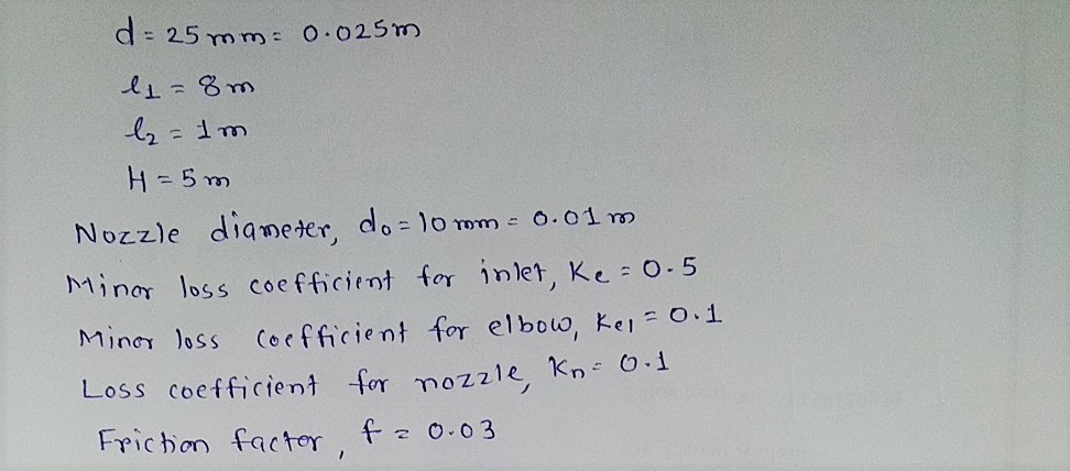
As shown in Fig. 4.33, the pipe diameter is d = 25 mm. l1 = 8 m; l2 = 1 m; H = 5 m. The nozzle diameter is d0 = 10 mm, and the minor loss coefficients of inlet and elbow are f1 = 0.5 and f2 = 0.1 respectively. For nozzle, f3 = 0.1 (relative to the outflow velocity of nozzle). The friction factor is k = 0:03. Try to determine jet height h.
As shown in Fig. 4.33, the pipe diameter is d = 25 mm. l1 = 8 m; l2 = 1 m; H = 5 m. The nozzle diameter is d0 = 10 mm, and the minor loss coefficients of inlet and elbow are f1 = 0.5 and f2 = 0.1 respectively. For nozzle, f3 = 0.1 (relative to the outflow velocity of nozzle). The friction factor is k = 0:03. Try to determine jet height h.
Elements Of Electromagnetics
7th Edition
ISBN:9780190698614
Author:Sadiku, Matthew N. O.
Publisher:Sadiku, Matthew N. O.
ChapterMA: Math Assessment
Section: Chapter Questions
Problem 1.1MA
Related questions
Question
As shown in Fig. 4.33, the pipe diameter is d = 25 mm. l1 = 8 m; l2 = 1 m;
H = 5 m. The nozzle diameter is d0 = 10 mm, and the minor loss coefficients
of inlet and elbow are f1 = 0.5 and f2 = 0.1 respectively. For nozzle, f3 =
0.1 (relative to the outflow velocity of nozzle). The friction factor is k = 0:03.
Try to determine jet height h.

Transcribed Image Text:**Fig. 4.33: Problem 4.18**
This diagram depicts a fluid flow scenario which involves a horizontal pipe leading from a reservoir and includes vertical sections. The following components and dimensions are specified:
- **Reservoir:** The leftmost section of the diagram represents the reservoir with a fluid level above the pipe outlet.
- **Horizontal Pipe Section:**
- Length \( l_1 \): The length of the horizontal pipe section from the reservoir to the elbow.
- Elevation \( \xi_1 \): The vertical position or elevation of the horizontal pipe.
- **Vertical Pipe Section:**
- Diameter \( d_0 \): The diameter of the vertical pipe section.
- Height \( h \): The height of the vertical section extending upwards.
- Elevation \( \xi_2 \): The vertical position or elevation at the bottom of the vertical section.
- **Intermediate Elevations** \(\xi_2\) and \(\xi_3\): These denote points at different heights along the vertical section of the layout.
- **Flow Direction:** The flow direction is indicated by arrows along the pipe path.
- **Overall Height \( H \):** The total vertical distance measured from the top of the reservoir to the end of the vertical pipe section.
The pipe appears to be arranged to transfer liquid from the reservoir to another point through a series of connected pipe segments, experiencing changes in elevation and direction. Understanding factors such as pressure changes, velocity, and flow rates would involve applying principles of fluid dynamics to this setup.
Expert Solution
Given

Step by step
Solved in 2 steps with 4 images

Recommended textbooks for you

Elements Of Electromagnetics
Mechanical Engineering
ISBN:
9780190698614
Author:
Sadiku, Matthew N. O.
Publisher:
Oxford University Press

Mechanics of Materials (10th Edition)
Mechanical Engineering
ISBN:
9780134319650
Author:
Russell C. Hibbeler
Publisher:
PEARSON

Thermodynamics: An Engineering Approach
Mechanical Engineering
ISBN:
9781259822674
Author:
Yunus A. Cengel Dr., Michael A. Boles
Publisher:
McGraw-Hill Education

Elements Of Electromagnetics
Mechanical Engineering
ISBN:
9780190698614
Author:
Sadiku, Matthew N. O.
Publisher:
Oxford University Press

Mechanics of Materials (10th Edition)
Mechanical Engineering
ISBN:
9780134319650
Author:
Russell C. Hibbeler
Publisher:
PEARSON

Thermodynamics: An Engineering Approach
Mechanical Engineering
ISBN:
9781259822674
Author:
Yunus A. Cengel Dr., Michael A. Boles
Publisher:
McGraw-Hill Education

Control Systems Engineering
Mechanical Engineering
ISBN:
9781118170519
Author:
Norman S. Nise
Publisher:
WILEY

Mechanics of Materials (MindTap Course List)
Mechanical Engineering
ISBN:
9781337093347
Author:
Barry J. Goodno, James M. Gere
Publisher:
Cengage Learning

Engineering Mechanics: Statics
Mechanical Engineering
ISBN:
9781118807330
Author:
James L. Meriam, L. G. Kraige, J. N. Bolton
Publisher:
WILEY