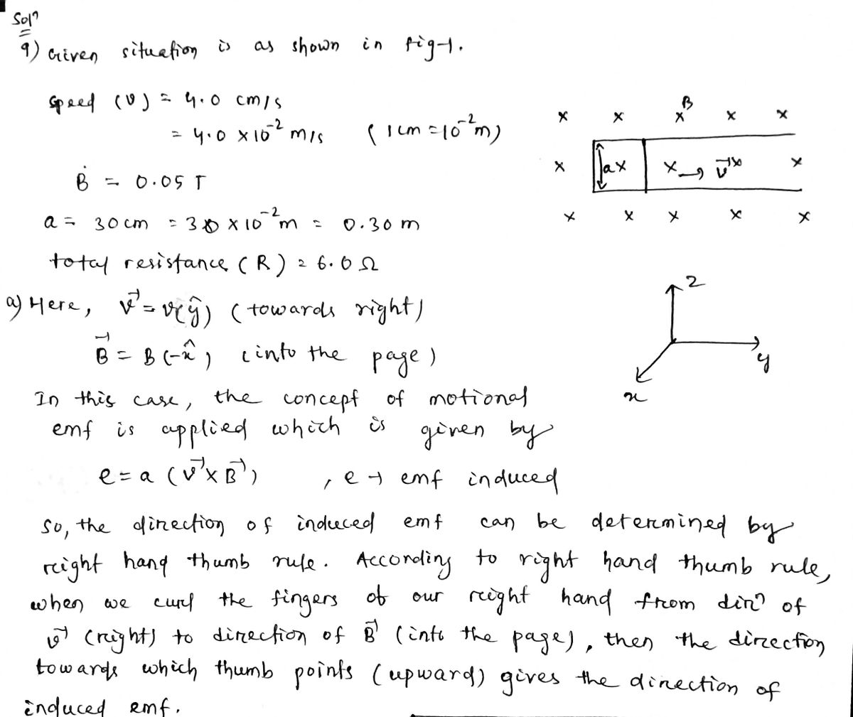
a. b. A metal frame (shown in gray) sits in a region of uniform magnetic field. A thin, rigid wire can slide along the side legs of the frame. Suppose the wire is pulled to the right with a speed of 4.0 cm/s and B = 0.05 T. Also, let a = 30 cm. The wire and frame have negligible electrical resistance but the contact resistance between the wire and the frame provides a total of 6.0 Ohms. Determine the direction of the induced current in the wire and frame circuit. Calculate the magnitude of the induced current in the wire and frame. Express your answer in milli-Amps.
a. b. A metal frame (shown in gray) sits in a region of uniform magnetic field. A thin, rigid wire can slide along the side legs of the frame. Suppose the wire is pulled to the right with a speed of 4.0 cm/s and B = 0.05 T. Also, let a = 30 cm. The wire and frame have negligible electrical resistance but the contact resistance between the wire and the frame provides a total of 6.0 Ohms. Determine the direction of the induced current in the wire and frame circuit. Calculate the magnitude of the induced current in the wire and frame. Express your answer in milli-Amps.
Related questions
Question

Transcribed Image Text:**Problem Statement:**
A metal frame (shown in gray) sits in a region of uniform magnetic field. A thin, rigid wire can slide along the side legs of the frame. Suppose the wire is pulled to the right with a speed of 4.0 cm/s and \( B = 0.05 \, \text{T} \). Also, let \( a = 30 \, \text{cm} \). The wire and frame have negligible electrical resistance but the contact resistance between the wire and the frame provides a total of 6.0 Ohms.
**Tasks:**
a. Determine the direction of the induced current in the wire and frame circuit.
b. Calculate the magnitude of the induced current in the wire and frame. Express your answer in milli-Amps.
**Diagram Explanation:**
- The diagram shows a rectangular metal frame with a movable wire on one side.
- The magnetic field is represented by blue crosses, indicating the field direction is perpendicular to the frame and into the plane of the diagram.
- The distance between the top and bottom of the frame in which the wire slides is labeled \( a = 30 \, \text{cm} \).
The aim is to analyze the induced electromotive force and current when the wire moves through this magnetic field.
Expert Solution
Step 1

Step by step
Solved in 3 steps with 3 images
