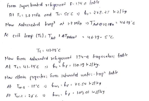
A commercial refrigerator with refrigerant-134a as the working fluid is used to keep the refrigerated space at -35°C by rejecting waste heat to cooling water that enters the condenser at 18°C at a rate of 0.35 kg/s and leaves at 26°C. The refrigerant enters the condenser at 1.2 MPa and 50°C and leaves at the same pressure subcooled by 5°C. The compressor consumes 3.3 kW of power. Use data from the tables. 26°C 1.2 MPa 5°C subcooled Expansion valve Condenser Evaporator 2₁ Water 18°C 1.2 MPa 50°C Compressor Determine the mass flow rate of the refrigerant. (You must provide an answer before moving to the next part.) The mass flow rate of the refrigerant is kg/s.
A commercial refrigerator with refrigerant-134a as the working fluid is used to keep the refrigerated space at -35°C by rejecting waste heat to cooling water that enters the condenser at 18°C at a rate of 0.35 kg/s and leaves at 26°C. The refrigerant enters the condenser at 1.2 MPa and 50°C and leaves at the same pressure subcooled by 5°C. The compressor consumes 3.3 kW of power. Use data from the tables. 26°C 1.2 MPa 5°C subcooled Expansion valve Condenser Evaporator 2₁ Water 18°C 1.2 MPa 50°C Compressor Determine the mass flow rate of the refrigerant. (You must provide an answer before moving to the next part.) The mass flow rate of the refrigerant is kg/s.

Elements Of Electromagnetics
7th Edition
ISBN:9780190698614
Author:Sadiku, Matthew N. O.
Publisher:Sadiku, Matthew N. O.
ChapterMA: Math Assessment
Section: Chapter Questions
Problem 1.1MA

Related questions
Question

Transcribed Image Text:**Educational Content on Refrigeration Cycle**
### Overview
This section provides a detailed explanation of a commercial refrigeration system using refrigerant-134a. The system is designed to maintain a refrigerated space at a temperature of -35°C by expelling waste heat to cooling water.
### System Description
- **Refrigerant:** R-134a
- **Refrigerated Space Temperature:** -35°C
- **Condenser Water Inlet Temperature:** 18°C
- **Condenser Water Outlet Temperature:** 26°C
- **Cooling Water Mass Flow Rate:** 0.35 kg/s
- **Condenser Pressure:** 1.2 MPa
- **Condenser Temperature:** 50°C, subcooled by 5°C
- **Compressor Power Consumption:** 3.3 kW
### Diagram Explanation
The refrigeration cycle consists of four main components, depicted in the schematic diagram:
1. **Compressor:**
- Increases the pressure and temperature of the refrigerant.
- Power input required is 3.3 kW.
2. **Condenser:**
- Heat exchange occurs here where hot refrigerant gas is cooled by water.
- Enters at 1.2 MPa and 50°C, with water entering at 18°C and leaving at 26°C.
3. **Expansion Valve:**
- Reduces the pressure and temperature of the refrigerant, preparing it for the evaporator.
4. **Evaporator:**
- Absorbs heat from the space to be cooled.
- Refrigerant transitions from a liquid to a gas.
### Task
**Objective:** Determine the mass flow rate of the refrigerant within the system.
**Calculations:**
- Use thermodynamic tables and the provided conditions to calculate the mass flow rate in kg/s.
**Question:**
- Determine the mass flow rate of the refrigerant.
**Answer Box:**
- The mass flow rate of the refrigerant is _____ kg/s.
This setup allows students to explore the application of thermodynamic principles in refrigeration and helps them calculate key parameters for efficient system operation.
Expert Solution
Step 1

Step by step
Solved in 2 steps with 2 images

Knowledge Booster


Learn more about
Need a deep-dive on the concept behind this application? Look no further. Learn more about this topic, mechanical-engineering and related others by exploring similar questions and additional content below.Recommended textbooks for you
Elements Of Electromagnetics
Mechanical Engineering
ISBN:
9780190698614
Author:
Sadiku, Matthew N. O.
Publisher:
Oxford University Press

Mechanics of Materials (10th Edition)
Mechanical Engineering
ISBN:
9780134319650
Author:
Russell C. Hibbeler
Publisher:
PEARSON

Thermodynamics: An Engineering Approach
Mechanical Engineering
ISBN:
9781259822674
Author:
Yunus A. Cengel Dr., Michael A. Boles
Publisher:
McGraw-Hill Education
Elements Of Electromagnetics
Mechanical Engineering
ISBN:
9780190698614
Author:
Sadiku, Matthew N. O.
Publisher:
Oxford University Press
Mechanics of Materials (10th Edition)
Mechanical Engineering
ISBN:
9780134319650
Author:
Russell C. Hibbeler
Publisher:
PEARSON
Thermodynamics: An Engineering Approach
Mechanical Engineering
ISBN:
9781259822674
Author:
Yunus A. Cengel Dr., Michael A. Boles
Publisher:
McGraw-Hill Education

Control Systems Engineering
Mechanical Engineering
ISBN:
9781118170519
Author:
Norman S. Nise
Publisher:
WILEY

Mechanics of Materials (MindTap Course List)
Mechanical Engineering
ISBN:
9781337093347
Author:
Barry J. Goodno, James M. Gere
Publisher:
Cengage Learning

Engineering Mechanics: Statics
Mechanical Engineering
ISBN:
9781118807330
Author:
James L. Meriam, L. G. Kraige, J. N. Bolton
Publisher:
WILEY