A - 150 kip-ft (negative 150 kip-feet) moment is acting at the centroid of the cross section shown on the next page. Determine the bending stress-in psi - at a point that is located (a) at the top surface of the cross section. (b) 3 inches down from the top surface of the cross section. (c) 12 inches up from the bottom surface of the cross section. (d) 3 inches up from the bottom surface of the cross section. (e) at the bottom surface of the cross section. M
A - 150 kip-ft (negative 150 kip-feet) moment is acting at the centroid of the cross section shown on the next page. Determine the bending stress-in psi - at a point that is located (a) at the top surface of the cross section. (b) 3 inches down from the top surface of the cross section. (c) 12 inches up from the bottom surface of the cross section. (d) 3 inches up from the bottom surface of the cross section. (e) at the bottom surface of the cross section. M
Elements Of Electromagnetics
7th Edition
ISBN:9780190698614
Author:Sadiku, Matthew N. O.
Publisher:Sadiku, Matthew N. O.
ChapterMA: Math Assessment
Section: Chapter Questions
Problem 1.1MA
Related questions
Question

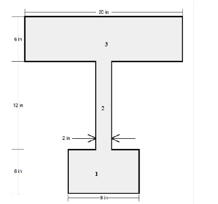
Transcribed Image Text:This diagram depicts a T-shaped structural component, showing various dimensions that define its geometry.
- The top horizontal section of the "T" is 20 inches wide and 6 inches tall.
- The vertical part of the "T" that connects the top and bottom sections is 12 inches tall and 2 inches wide.
- At the bottom of the "T," the horizontal section measures 9 inches in width and 6 inches in height.
This T-beam shape is commonly used in construction and structural engineering to provide support where a large load-bearing capacity is needed. The measurements detailed in the diagram help in determining the beam's capacity to bear loads and its application in different structural scenarios.

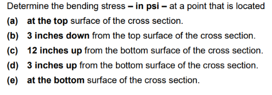
Transcribed Image Text:**Problem 2: Bending Stress Analysis**
A moment of -150 kip-ft (negative 150 kip-feet) is acting at the centroid of the cross section shown.
**Objective**: Determine the bending stress in psi at specific points on the cross section.
**Points of Interest**:
(a) At the top surface of the cross section.
(b) 3 inches down from the top surface of the cross section.
(c) 12 inches up from the bottom surface of the cross section.
(d) 3 inches up from the bottom surface of the cross section.
(e) At the bottom surface of the cross section.
**Diagram Overview**:
The accompanying diagram illustrates a beam with an I-shaped cross section. A negative moment \( M \) is acting at the centroid. Arrows are pointing towards the left, indicating the direction of the forces associated with the moment.
**Concepts Utilized**: Bending stress calculations use the formula \(\sigma = \frac{M \cdot c}{I}\), where:
- \( \sigma \) is the bending stress,
- \( M \) is the moment,
- \( c \) is the distance from the neutral axis to the point of interest,
- \( I \) is the moment of inertia of the cross section.
This setup is a typical problem to evaluate the distribution of stresses within beam structures, critical in structural engineering and materials science.
Expert Solution
Step 1: Write the given data and what is to find
Given:

To find:

Step by step
Solved in 8 steps with 21 images

Knowledge Booster
Learn more about
Need a deep-dive on the concept behind this application? Look no further. Learn more about this topic, mechanical-engineering and related others by exploring similar questions and additional content below.Recommended textbooks for you

Elements Of Electromagnetics
Mechanical Engineering
ISBN:
9780190698614
Author:
Sadiku, Matthew N. O.
Publisher:
Oxford University Press

Mechanics of Materials (10th Edition)
Mechanical Engineering
ISBN:
9780134319650
Author:
Russell C. Hibbeler
Publisher:
PEARSON

Thermodynamics: An Engineering Approach
Mechanical Engineering
ISBN:
9781259822674
Author:
Yunus A. Cengel Dr., Michael A. Boles
Publisher:
McGraw-Hill Education

Elements Of Electromagnetics
Mechanical Engineering
ISBN:
9780190698614
Author:
Sadiku, Matthew N. O.
Publisher:
Oxford University Press

Mechanics of Materials (10th Edition)
Mechanical Engineering
ISBN:
9780134319650
Author:
Russell C. Hibbeler
Publisher:
PEARSON

Thermodynamics: An Engineering Approach
Mechanical Engineering
ISBN:
9781259822674
Author:
Yunus A. Cengel Dr., Michael A. Boles
Publisher:
McGraw-Hill Education

Control Systems Engineering
Mechanical Engineering
ISBN:
9781118170519
Author:
Norman S. Nise
Publisher:
WILEY

Mechanics of Materials (MindTap Course List)
Mechanical Engineering
ISBN:
9781337093347
Author:
Barry J. Goodno, James M. Gere
Publisher:
Cengage Learning

Engineering Mechanics: Statics
Mechanical Engineering
ISBN:
9781118807330
Author:
James L. Meriam, L. G. Kraige, J. N. Bolton
Publisher:
WILEY