5-65 Find vo in the following circuit, 6 mV 50 ΚΩΤ ww R1 Ans: V1 = 6 mV; _V2 = - V1 R2 10 ΚΩ ww R3 30 ΚΩ www V2 R4 20 ΚΩ ww R6 40 ΚΩ 18 mV; Vo= – 21.6 mV www 8 ΚΩ R5 Vo
5-65 Find vo in the following circuit, 6 mV 50 ΚΩΤ ww R1 Ans: V1 = 6 mV; _V2 = - V1 R2 10 ΚΩ ww R3 30 ΚΩ www V2 R4 20 ΚΩ ww R6 40 ΚΩ 18 mV; Vo= – 21.6 mV www 8 ΚΩ R5 Vo

Introductory Circuit Analysis (13th Edition)
13th Edition
ISBN:9780133923605
Author:Robert L. Boylestad
Publisher:Robert L. Boylestad
Chapter1: Introduction
Section: Chapter Questions
Problem 1P: Visit your local library (at school or home) and describe the extent to which it provides literature...

Related questions
Question

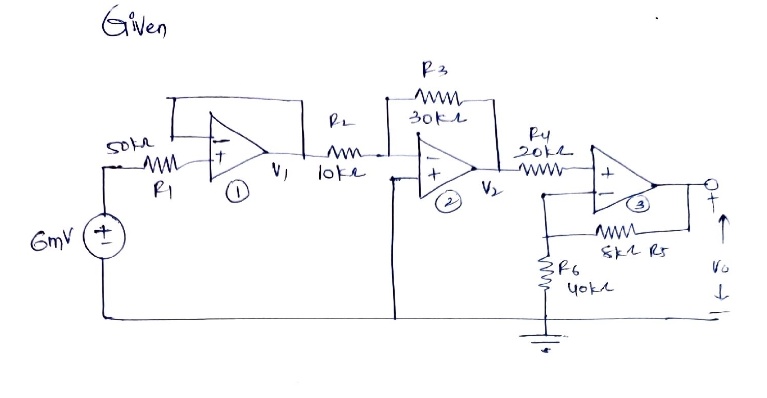
Transcribed Image Text:**Figure Description:**
The circuit diagram shown is an op-amp based configuration with various resistors connected in specific configurations. Below is a detailed explanation:
1. **Voltage Source:** There is a voltage source of 6 mV connected to the circuit.
2. **Resistor and Op-Amp Setup:**
- **R1 (50 kΩ):** Connected directly to the voltage source and the non-inverting input of the first op-amp.
- **Op-Amp 1:** The non-inverting input (+) is connected through R1 to the 6 mV source. The output is labeled as \( V_1 \).
- **R2 (10 kΩ):** Connected from the output of the first op-amp \( V_1 \) to the inverting input (-) of the same op-amp.
3. **Second Stage of the Circuit:**
- **R3 (30 kΩ):** Connected from the output \( V_1 \) of the first op-amp to the inverting input of the second op-amp.
- **Op-Amp 2:** The inverting input (-) is connected through R3. The output is labeled as \( V_2 \).
- **R6 (40 kΩ):** Connected from the inverting input of the second op-amp to the ground.
- **R4 (20 kΩ):** Connected from the output of the second op-amp \( V_2 \) to the non-inverting input of the same op-amp.
4. **Final Stage of the Circuit:**
- **R5 (8 kΩ):** Connected from the non-inverting input of the third op-amp to the output of the second op-amp.
- **Op-Amp 3:** The non-inverting input (+) receives input from \( V_2 \) through R5. The output is indicated as \( v_o \), which is the desired output voltage of the entire circuit.
**Problem Statement:**
- The task is to find \( v_o \) in the given circuit.
**Solution:**
- The answers provided are:
- \( V_1 = 6 \, \text{mV} \)
- \( V_2 = -18 \, \text{mV} \)
- \( v_o = -21.6 \, \text
Expert Solution
Step 1

Step by step
Solved in 2 steps with 2 images

Knowledge Booster


Learn more about
Need a deep-dive on the concept behind this application? Look no further. Learn more about this topic, electrical-engineering and related others by exploring similar questions and additional content below.Recommended textbooks for you
Introductory Circuit Analysis (13th Edition)
Electrical Engineering
ISBN:
9780133923605
Author:
Robert L. Boylestad
Publisher:
PEARSON

Delmar's Standard Textbook Of Electricity
Electrical Engineering
ISBN:
9781337900348
Author:
Stephen L. Herman
Publisher:
Cengage Learning

Programmable Logic Controllers
Electrical Engineering
ISBN:
9780073373843
Author:
Frank D. Petruzella
Publisher:
McGraw-Hill Education
Introductory Circuit Analysis (13th Edition)
Electrical Engineering
ISBN:
9780133923605
Author:
Robert L. Boylestad
Publisher:
PEARSON
Delmar's Standard Textbook Of Electricity
Electrical Engineering
ISBN:
9781337900348
Author:
Stephen L. Herman
Publisher:
Cengage Learning
Programmable Logic Controllers
Electrical Engineering
ISBN:
9780073373843
Author:
Frank D. Petruzella
Publisher:
McGraw-Hill Education

Fundamentals of Electric Circuits
Electrical Engineering
ISBN:
9780078028229
Author:
Charles K Alexander, Matthew Sadiku
Publisher:
McGraw-Hill Education

Electric Circuits. (11th Edition)
Electrical Engineering
ISBN:
9780134746968
Author:
James W. Nilsson, Susan Riedel
Publisher:
PEARSON

Engineering Electromagnetics
Electrical Engineering
ISBN:
9780078028151
Author:
Hayt, William H. (william Hart), Jr, BUCK, John A.
Publisher:
Mcgraw-hill Education,