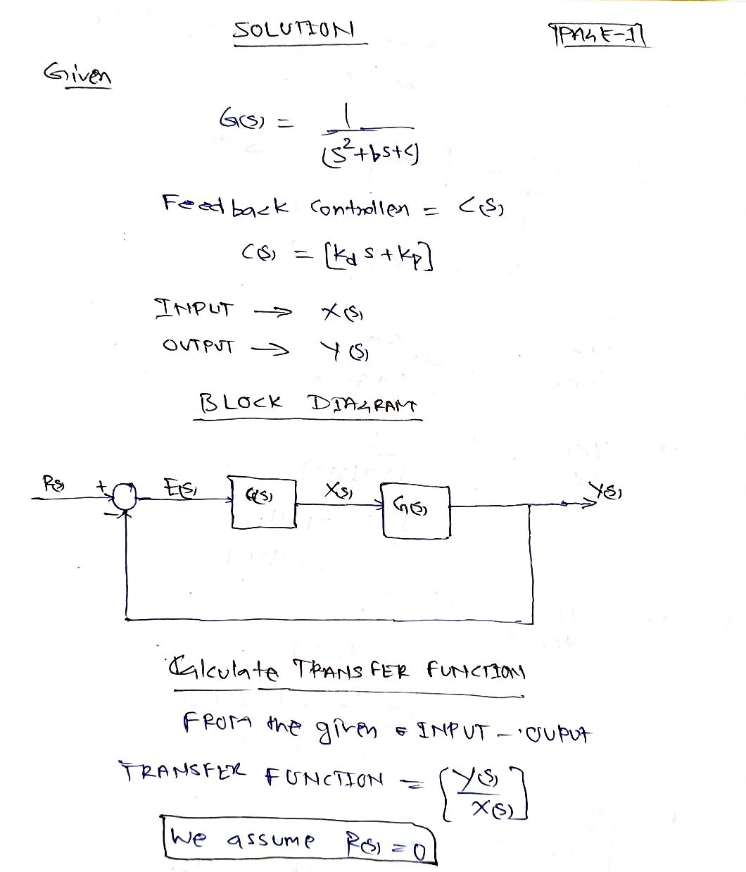
3. Consider a generic plant system with transfer function G(s) = from (plant) input signal X (s) to output signal Y(s). Assume a feedback controller C(s) = Kas+Kp is placed in the "design" configuration, i.e., R(s) E(s) C(s) 1 s2+bs+c X(s) G(s) Determine any restrictions on K, and/or K, necessary for the closed-loop system to be stable. Your answer(s) may be functions of the plant parameters b and c.
3. Consider a generic plant system with transfer function G(s) = from (plant) input signal X (s) to output signal Y(s). Assume a feedback controller C(s) = Kas+Kp is placed in the "design" configuration, i.e., R(s) E(s) C(s) 1 s2+bs+c X(s) G(s) Determine any restrictions on K, and/or K, necessary for the closed-loop system to be stable. Your answer(s) may be functions of the plant parameters b and c.

Introductory Circuit Analysis (13th Edition)
13th Edition
ISBN:9780133923605
Author:Robert L. Boylestad
Publisher:Robert L. Boylestad
Chapter1: Introduction
Section: Chapter Questions
Problem 1P: Visit your local library (at school or home) and describe the extent to which it provides literature...

Related questions
Question
Although we are given the restrictions on Kd and Kp, explain how we arrived at that conclusion and show all work necessary to arrive at the given solution for each restriction.

Transcribed Image Text:3. Need \( K_d \gg -b \) and \( K_p \gg -c \)
![# Analysis of a Generic Plant System with Feedback Control
### Transfer Function
Consider a generic plant system with the transfer function given by:
\[
G(s) = \frac{1}{s^2 + bs + c}
\]
This function describes the relationship from the plant input signal \( X(s) \) to the output signal \( Y(s) \).
### System Configuration
A feedback controller is included in the system, defined as:
\[
C(s) = K_d s + K_p
\]
This controller is placed in a feedback loop configuration, contributing to the design of the system.
#### Feedback Loop Diagram
The configuration is depicted in the block diagram:
1. **Summing Junction**: The diagram begins with a summing junction, where the reference signal \( R(s) \) is input and the error signal \( E(s) \) is produced.
2. **Controller Block**: The error signal \( E(s) \) is processed through the controller \( C(s) \), which adjusts the dynamics based on the parameters \( K_d \) and \( K_p \).
3. **Plant Block**: The output from the controller \( X(s) \) continues to the plant, represented by \( G(s) \), and produces the final system output \( Y(s) \).
4. **Feedback Path**: The output \( Y(s) \) is fed back to the summing junction to close the loop, influencing the error signal.
### Stability Analysis
The task involves determining any necessary restrictions on \( K_d \) and/or \( K_p \) for the closed-loop system to remain stable. The solution will consider these controller parameters as functions of the plant's parameters \( b \) and \( c \).
It's crucial to ensure system stability for effective operation, preventing oscillations or divergence over time.
### Conclusion
This setup is essential in control systems engineering, where stability and feedback loops are fundamental concepts. By adjusting \( K_d \) and \( K_p \), one can achieve desired performance characteristics while maintaining system stability.
This exploration forms a foundational step in understanding dynamic systems and control theory.](/v2/_next/image?url=https%3A%2F%2Fcontent.bartleby.com%2Fqna-images%2Fquestion%2F2de2484e-8c30-4a24-aa43-7ad85b110ab5%2Ffc540408-ecfe-459e-a38b-c43d7f873030%2Fllcko6c_processed.png&w=3840&q=75)
Transcribed Image Text:# Analysis of a Generic Plant System with Feedback Control
### Transfer Function
Consider a generic plant system with the transfer function given by:
\[
G(s) = \frac{1}{s^2 + bs + c}
\]
This function describes the relationship from the plant input signal \( X(s) \) to the output signal \( Y(s) \).
### System Configuration
A feedback controller is included in the system, defined as:
\[
C(s) = K_d s + K_p
\]
This controller is placed in a feedback loop configuration, contributing to the design of the system.
#### Feedback Loop Diagram
The configuration is depicted in the block diagram:
1. **Summing Junction**: The diagram begins with a summing junction, where the reference signal \( R(s) \) is input and the error signal \( E(s) \) is produced.
2. **Controller Block**: The error signal \( E(s) \) is processed through the controller \( C(s) \), which adjusts the dynamics based on the parameters \( K_d \) and \( K_p \).
3. **Plant Block**: The output from the controller \( X(s) \) continues to the plant, represented by \( G(s) \), and produces the final system output \( Y(s) \).
4. **Feedback Path**: The output \( Y(s) \) is fed back to the summing junction to close the loop, influencing the error signal.
### Stability Analysis
The task involves determining any necessary restrictions on \( K_d \) and/or \( K_p \) for the closed-loop system to remain stable. The solution will consider these controller parameters as functions of the plant's parameters \( b \) and \( c \).
It's crucial to ensure system stability for effective operation, preventing oscillations or divergence over time.
### Conclusion
This setup is essential in control systems engineering, where stability and feedback loops are fundamental concepts. By adjusting \( K_d \) and \( K_p \), one can achieve desired performance characteristics while maintaining system stability.
This exploration forms a foundational step in understanding dynamic systems and control theory.
Expert Solution
Step 1

Step by step
Solved in 3 steps with 3 images

Knowledge Booster


Learn more about
Need a deep-dive on the concept behind this application? Look no further. Learn more about this topic, electrical-engineering and related others by exploring similar questions and additional content below.Recommended textbooks for you
Introductory Circuit Analysis (13th Edition)
Electrical Engineering
ISBN:
9780133923605
Author:
Robert L. Boylestad
Publisher:
PEARSON

Delmar's Standard Textbook Of Electricity
Electrical Engineering
ISBN:
9781337900348
Author:
Stephen L. Herman
Publisher:
Cengage Learning

Programmable Logic Controllers
Electrical Engineering
ISBN:
9780073373843
Author:
Frank D. Petruzella
Publisher:
McGraw-Hill Education
Introductory Circuit Analysis (13th Edition)
Electrical Engineering
ISBN:
9780133923605
Author:
Robert L. Boylestad
Publisher:
PEARSON
Delmar's Standard Textbook Of Electricity
Electrical Engineering
ISBN:
9781337900348
Author:
Stephen L. Herman
Publisher:
Cengage Learning
Programmable Logic Controllers
Electrical Engineering
ISBN:
9780073373843
Author:
Frank D. Petruzella
Publisher:
McGraw-Hill Education

Fundamentals of Electric Circuits
Electrical Engineering
ISBN:
9780078028229
Author:
Charles K Alexander, Matthew Sadiku
Publisher:
McGraw-Hill Education

Electric Circuits. (11th Edition)
Electrical Engineering
ISBN:
9780134746968
Author:
James W. Nilsson, Susan Riedel
Publisher:
PEARSON

Engineering Electromagnetics
Electrical Engineering
ISBN:
9780078028151
Author:
Hayt, William H. (william Hart), Jr, BUCK, John A.
Publisher:
Mcgraw-hill Education,